WITH
NOTES ON THE METHODS USED FOR THE
DISTRIBUTION OF ELECTRICITY.
BY
KILLINGWORTH HEDGES,
MEMBER OF THE INSTITUTION OF CIVIL ENGINEERS, AND OF
THE SOCIETY OF TELEGRAPH ENGINEERS AND ELECTRICIANS.
LONDON:
E. & F. N. SPON, 125, STRAND.
NEW YORK: 12, CORTLANDT STREET.
[All rights reserved.]
The art of lighting by Electricity practically dates from ten years ago, and it has during that period received the constant attention of both Electrical Engineers and others, who have applied the greatest scientific knowledge. The result of all this energy appears to be discouraging. Five hundred thousand pounds have been subscribed to carry on the business, and it is doubtful whether the companies which survive have a market value of one-tenth of that sum. The experience may have been bought too dearly, but the era of Central-Station Electric Lighting, which has now commenced, ought to re-establish the position of Electricity in financial circles, and afford a safe and profitable outlet for the surplus capital of the investor who buys gas and water shares to pay four per cent.
The distribution of electricity from a central-station, which was the subject of Sir William Siemen’s Presidential Address at the Society of Arts in 1882, is not only accomplished from the scientific point of view, but is also a commercial success: the power of flowing water, or [Pg vi] the potential energy stored up in coal, wood, or other fuel, can be utilised for lighting our streets and houses at night, and during the day may be transmitted by means of electricity in the easiest possible way, and supplant the gas-engine for driving small machinery.
A paper entitled “Central-Station Electric Lighting” was contributed by the Author to the Institution of Civil Engineers, and was published in Part II. of the Minutes, 1886-87; the subject-matter has been extended and brought up to date, with the object of giving a description of the systems which are practically employed in Central-Station Lighting at home and on the Continent. Details respecting the generating plant at these stations are omitted on purpose; technical terms would also be avoided if possible; failing this, it is hoped that the accompanying Glossary will explain what is unfamiliar.
The amendment of the Electric Lighting Act of 1882 has given a fresh stimulus to the industry, and many new enterprises for distributing electricity from Central-Stations are being prepared, and it is to be hoped that the public will profit by former experience, and will discriminate between the good and the bad schemes which will be offered to them.
The organizing facilities possessed by Gas Companies make it desirable that they should follow the example of the American Companies, and take up the business of supplying electricity. The existing powers of [Pg vii] private companies might have to be altered, but those municipal authorities who own the gasworks could certainly distribute electricity from a central-station, which might be installed at the present works. Local authorities have certain advantages over private companies owing to the purchasing clause of the Electric Lighting Act, also the power to borrow money under this and the Local Loans Act of 1875; should there be no department to carry out the business of supplying electricity, the generating plant could be maintained and worked by a contractor for a fixed annual sum.
The remarks of Lord Herschell that the “electric light is more used in the South Sea Islands than in this country” ought to be taken as not so much referring to want of enterprise on the part of capitalists and engineers, but to the Electrical Facilities Act of 1882, which has been appropriately termed a very “boa-constrictor.”
25,Queen Anne’s Gate,
Westminster, S.W.
September, 1888.
AS the term “central-station” associates itself with some pretentious building, such as a railway terminus, it may be advisable to remark that the similarity is only in the words, and that central-station is an abbreviation of central generating station, or building designed to contain the plant for the public supply of electricity. In the early days of electric lighting the transmission of electricity to a distance was considered an impossibility; we find the late Sir William Siemens, in his Presidential Address at the Society of Arts on the occasion of the opening of the session in 1882, stating “that a quarter of a mile in every direction from the lighting station was the area which would be as much as could be economically worked;” and, in order to tap the most paying district, it was proposed to establish a station in the most central spot. Sir William Siemens suggested the utilisation of the public squares, which could be excavated to a depth of twenty-five [Pg 2] feet, and then arched over to the existing ground level, and in this covered space the engines, boilers, and dynamos were to be fixed; the only erection above the surface was the chimney, which was to be of ornamental design and combined with the ventilating arrangements of the subterranean chamber. The great inventor, who so ably filled the presidential chair at the meeting where these words were spoken, would be astonished to find that in London one electric lighting company has already erected seventy miles of overhead wire, and that customers are supplied miles away from the so-called central-station. The changed position of electricity is due to the introduction of the transformer by Goulard, who showed, at the Turin Exhibition of 1884, that a high-tension current could be transformed into a low-tension working current of safe potential, fifty miles away from the generator, in a successful and economical manner, and that the generating station might, therefore, be located outside the area to be lighted. In large cities this is a great advantage, the value of land often precluding the erection of a big station in the working area; for this reason small stations are often arranged in basements, under a large building, which are, as a rule, specially designed. This plan is somewhat similar to that adopted in the United States, where it is not unusual to find a successful installation in a basement and sub-basement, the general arrangement being of similar character to the engine-room of a steamship.
A station is being erected in Philadelphia on a ground space of 72 feet × 100 feet, which is to supply 60,000 lights; the building is [Pg 3] six-storied, the dynamos are on the first floor, the boilers on third, the coal stores on fourth, and the offices on the fifth.
The term “block station” is also used in the United States and in Germany, and is applied to an installation which lights a group of buildings or block without crossing any streets, and consequently without having any wayleave or permission from local authorities.
An American electrical engineer graphically sums up this question in the following manner:—“There are two ways of starting a central-station for electric lighting—the investment or the speculative plan, or the fair means or the foul. The first has its legitimate end, but the latter is the border ruffian or money-or-your-life policy, which enters a territory already sufficiently covered, not for fair competition, but to make money by being bought out.” Happily, here, we have at present only to deal with the first plan, and the question naturally arises, “Is electric lighting a paying investment?” It certainly will not be if the object in view is only to compete with gas in a limited district where perhaps it is being sold at 2s. 6d. per 1000 feet, for, as long as there is a ready market for the coke and other by-products, gas will remain in possession of the field. The heat from gas, which is found so undesirable by the wealthier classes, is advantageous to those who [Pg 4] perhaps cannot afford a fire; in fact, gas has been truly called the “poor man’s friend,” and, until electricity can be supplied at a nominal price, it will be useless to expect any revenue from the poorer districts of large cities. Quite an opposite result may be looked for when the electric mains are laid at the doors of the wealthy householder, or through the business neighbourhoods. Shop-owners especially are found to immediately take up electric light, from the fact that no fumes are given off to destroy goods or tarnish silver or gilding, and because it can be so easily applied in a shop window so as to efficiently light the contents without producing shadows. The great object to be aimed at in selecting a district to be served from a central-station is a “constant demand,” and for this reason it is advantageous to include a business neighbourhood with shops, public-houses, and restaurants, which require the light for a definite period every day, and probably will each take more than double the amount of an ordinary dwelling-house; in fashionable neighbourhoods especially, it is not unusual to find a large number of houses vacated at the close of the season, the interest on that portion of the electric system which is unemployed will have to be set against the profits of other periods of the year.
The number of gas lights which are actually used at one time in a house is found to average only two-thirds of the total number fixed, and with electric light this number is reduced to one-half; economy is at once the rule with electric light, partly because of the novelty of the illuminant, and also on account of the facility of lighting and extinguishing by simply turning a tap or switch. The number of hours artificial light is wanted in a residential district may be taken at [Pg 5] about 1000 hours per annum, that is to say, the light is required for about four hours a day in winter and two hours in summer; this amount is very much exceeded in clubs, shops, and even in large houses, but 1000 hours is a safe figure, and, if the supply is taken by meter, an annual payment equivalent to 1000 hours’ supply should be a fixed amount to be paid for, whether used or not. Mr. Crompton estimates that a Londoner, who is a tenant or owner of a house having three reception rooms, ten bedrooms, and usual offices, spends about £25 a year for his lighting, which is made up as follows:—gas bill, £15; lamp, oil, candles, matches, about £10. There would be about fifty burners fixed; and, supposing fifty electric lights to be substituted, he could be supplied with electricity for £25 a year, at a fair profit to the supply company if they charged 8d. per Board of Trade Unit, as practice has shown that the total number of lamp-hours with fifty electric lamps is not more than sixty-two, so that two Units,[1] or 1s. 4d. per day, would be sufficient for the lights he would require.
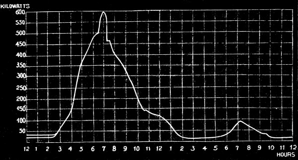
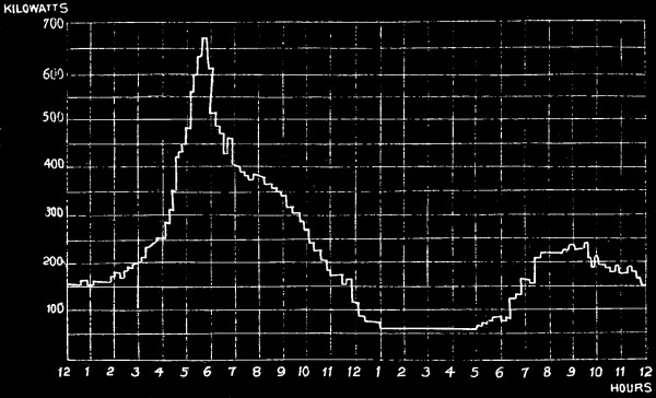
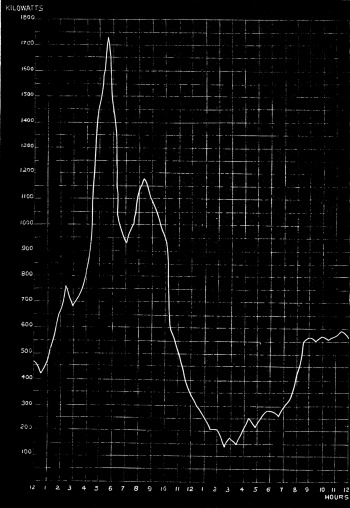
The diagram, Fig. 1, taken from a London residential district, shows how the number of lamps on at one time vary; the district is supposed to be wired for 10,000 lamps, and the plant as equal to the supply of 600 kilowatts, or 600,000 watts; the number of lamps is small until about 3 o’clock, when it gets dusk on a winter afternoon; it then increases steadily until about 6.30 o’clock, when the curve goes up with a rush; about this time a great number of people are preparing for [Pg 6] dinner, and probably the lights are on both in the dining-room and bedrooms. The curve falls, and at about 8 it begins to sink gradually until 10 o’clock; a great many people appear to go to bed about this time, but a few sit up to 1 o’clock; until 6 the next morning hardly any supply is taken, when the servants get up and prepare the rooms for the day. The diagram, Fig. 2, is taken from the Edison Company’s central-station at Cincinnati, and agrees fairly with the London demand for light. Another interesting fact has been ascertained from the observations taken at the Mauer Strasse station in Berlin, namely, that the output varies with the temperature, it goes up or down with the thermometer. The reason is easily explained; gas is laid on side by side with the incandescent lamps, and the burners are first lighted when it is cold to warm the apartments; in warm weather the electric light alone is used. From these and other diagrams the very important [Pg 7] fact has been obtained, that the average daily output of a station throughout the year is less than one-third of the total capacity of the generating machinery, so that, although the station from which the diagram in Fig. 1 was taken could maintain 10,000 16 candle-power lamps simultaneously alight, the average daily output of electricity would only equal 3500 constantly lighted; and, as the first cost of the station is dependent on the size of the plant, the saleable output is the important factor which governs the profits.
The well-known expression “per 1000 Cubic Feet” is not applicable to electric light, and, instead, the Board of Trade Unit is employed. By [Pg 8] this term Unit is meant the quantity of energy contained in a current of 1000 Ampères flowing under an Electro-motive Force of One Volt during One Hour. In the early days of electric lighting the term Volt-ampère was used, and has for convenience sake been shortened to Watt; that is, the Volt or Unit of Electro-motive Force (or pressure) is multiplied by the Ampère or Unit of current.
The Board of Trade Unit is, therefore, a Thousand Volt-ampères or Watts per hour.
For example: 16 candle-power Swan lamps are assumed to take 60 Watts, which, if the electrical pressure is 100 Volts, would mean a consumption of 0·6 Ampère; and, as an Electrical Horse-power equals 746 Watts, 12·4 lamps should theoretically be obtained per Horse-power, which is, however, reduced in actual practice to 10 at the most, often less.
The charge per Unit supplied by meter varies in England from 1s. to 7d.
| Price for electric light. |
Equivalent price for gas of equal light. |
||||||
|---|---|---|---|---|---|---|---|
| s. | d. | s. | d. | ||||
| 1 | 0 | per Board | 6 | 10 | per 1000 cubic feet. | ||
| 0 | 9 | of | 5 | 1½ | ”” | ||
| 0 | 7¼ | Trade | 4 | 2 | ”” | ||
| 0 | 6 | Unit. | 3 | 5 | ”” | ||
These prices, of course, include the manufacturer’s profit as well as the loss in transmission through the mains and expenses of connecting up to the consumer. The actual manufacturing cost of a station [Pg 9] maintaining 10,000 lights should not be more than 3d. per Unit, or equivalent to gas at 1s. 8½d. per 1000 cubic feet.[2]
As petroleum lamps are used for the street lighting of many foreign and colonial towns, the question arises, “Will it pay to substitute the electric light?” Comparing the light given by a kerosene or petroleum lamp with that from the incandescent electric lamp, the cost is greatly in favour of oil; and, in fact, where the price of kerosene is under 1s. per gallon, electricity cannot compete if labour is cheap. On the other hand, the trimming, lighting, and keeping in order of a number of lamps scattered over a large area greatly augments the working cost, to which must be added the breakages of chimneys, expense of wicks, also the danger of fire. It is the safety of electricity which has caused it to supplant oil both for public and private lighting in American cities; even where the price of kerosene is not more than 6d. per gallon there is a demand for the electric light, which is by far the dearer illuminant, after making a liberal allowance for labour in cleaning, filling, and lighting the oil lamp, also for depreciation of the burners.
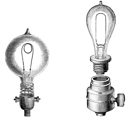
Electric lighting can be obtained by means of arc or incandescent lamps. The arc light is now well understood to be caused by the extremely high temperature of the end of one or both the carbon [Pg 10] electrodes. The voltaic arc, Fig. 3, is formed by the minute particles of carbon in a high state of combustion which the current appears to break off and carry from one electrode to the other, the light, however, being mainly due to the incandescence of the crater shown in Fig. 3 on the upper carbon. In the incandescent or glow lamp light is produced by the passage of a current of electricity through a continuous fine thread or filament of carbon which becomes white-hot, the destruction of the filament being prevented through its enclosure in a glass bulb from which the air is exhausted. Figs. 4 and 5.
The first method is suitable for the lighting of streets where a high-class illumination is required; also will be wanted for the external lighting of shops, public-houses, and places of amusement, so that arrangements must be made for arc lighting. The usual plan is to charge at the same rate per Unit by meter as the incandescent lamps, but to make an additional charge of 5s. to 7s. 6d. per lamp per quarter for rent, and a further charge of 3s. per week for cleaning and trimming.
The principal types are the Edison and the Swan, Fig. 4 and Fig. 5.
Incandescent lamps can be obtained to order from 1½ candle-power upwards, but the 16 candle-power (nominal 20) or the 8 candle-power (nominal 10) lamps are almost invariably employed. The latter give the best effect, and can be worked to 10 candle-power without much risk, [Pg 11] they take about 30 watts as against 60 watts for the 16 candles; and are not uneconomical, for nearly double the number can be worked with the same energy. A new type of glow lamp, called the “Sunbeam,” has been recently introduced, which contains a thick filament, and gives a light of from 200 to 1500 candle-power, and can be employed instead of an arc lamp with the same economy as the ordinary 16 candle-power type.
In estimating the annual cost of lighting, the renewals of lamps must be taken into account; and although some lamps have worked 3000 or even 4000 hours, a life of 1000 working hours is the highest average it is [Pg 12] safe to assume in practical work under even the best conditions, that is, using secondary batteries and never over running. The average life of 130 lamps on H.M.S. troopship Malabar was 3799 hours each, the shortest life being 638½ hours for 18 yard-arm lamps of 32 candle-power. If the current is allowed to fluctuate, the average life would be very much less; it is an unsettled question whether long-lived lamps are really economical, by reason of the blackening of the globes, which takes place after the lamp has been worked some time, and is probably due to small particles of carbon thrown off from the filament being deposited on the glass. It has been suggested that attrition of the filament is going on all the time the lamp is at work, and that the heated atoms striking against the filament may account for the blackening, in that the mean free path of the atoms would be greater in a perfect vacuum than in the air, consequently they would abrade the filament with considerable force. If lamps were sold at 1s. each instead of 3s. 6d., which is now the price for not less than a thousand, it would be more economical to change them at the first signs of blackening, even if the life did not exceed 500 hours.
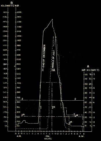
The diagram, Fig. 6, has been so arranged that the amount of light required in a given district can be ascertained for any period of the day or night; it has been calculated from the observations taken daily at one of the Berlin central-stations by the engineer to the company.
Six hundred and forty watts are assumed, for the purposes of the [Pg 13] diagram, to be the equivalent of a horse-power, instead of 736, as the German electrical horse-power is 736 watts instead of 746 watts.
The table, Fig. 6, has two vertical scales, A and B, each giving the [Pg 14] kilowatts[3] and corresponding horse-power. A is drawn to a scale ten times greater than B, with the object of noting the smaller amount of lights required for street illumination. The horizontal line is divided into hours, and represents a day’s lighting in the middle of December and the end of July, so as to show the maximum and minimum amount of current that will be required. In the lighting of a town there are two classes of illumination, the amount taken by the public, which is uncertain, and that employed for street lighting, which is a known quantity.
The curves, II and II A, represent the private lighting of houses, hotels, theatres, and shops of different kinds in December and in July, the curve, II A, being in dotted lines clearly shows what a vast difference there is in the amount of light, and consequently the amount of energy required in the generating station, as compared with curve II, which is taken when the days are longest.
The rectangles, I and I A, show the street illumination, and are drawn to suit scale A; half an hour after sunset all the lamps are turned on, and the work reaches its maximum suddenly, and continues the same until 12 o’clock, when, according to the municipal decrees, it either falls one or two gradations until half an hour before sunrise, when all the lamps are extinguished. The calculations are based on the assumption of 640 watts to the horse-power, instead of 736, which is the theoretical efficiency of a German horse-power.
If a number of diagrams are taken on this method for different periods [Pg 15] of the year, the constant work can be ascertained. This knowledge is most valuable when calculating the most economical area for the mains, which is then easily accomplished by means of Forbes’ tables, which are based on Sir William Thomson’s well-known rule.
The lines, 2 and 2 a show the constant work at the same two periods of the year from which the diagrams are taken. The constant work at the end of December will be found to amount to 20 per cent. of the total work, and that at the middle of June to 15 per cent. By summing up the average work for all the days in the year we obtain the cost per annum, and adding to this the expense of management, interest, &c., and knowing the local conditions, we can fix what proportion of the day’s work is admissible as loss. With the Edison system at Berlin, 5 per cent. is taken as average loss; thus, at the end of December, it amounts, with the maximum number of lights, to 18·8 per cent., and with the minimum to 1·1 per cent.; in the middle of July the maximum is 15·8 per cent., and the minimum 0·5 per cent. The dynamos must, of course, be of sufficient power to be able to overcome this loss, which only shows itself periodically; therefore the generating plant may be constructed to give, nominally, 20 to 30 per cent. less than the maximum work, and be capable of being pushed to the full amount for a short time only. [Pg 16]
Uncontrolled financial speculation, aided by the stringent clauses of the Electric Lighting Act of 1882, have been a great deterrent to the extension of old or the introduction of new schemes for the supply of electricity to the public in the same manner as gas. The President of the Board of Trade, replying to a question in the House of Commons, said that, “since the passing of the Electric Lighting Act of 1882, fifty-nine provisional orders and five licences had been granted to companies, and fifteen provisional orders and two licences to local authorities. He was not aware that, in any single case where these powers had been obtained, they had been exercised.” Up to the present time no company supplying electricity has been under the necessity of applying for compulsory powers, and has either obtained permission from the local authorities to take up the streets, or has carried the electric mains over the houses, and, regardless of the question of overhead wires, has depended on wayleaves granted by the too-confiding householder, who has no idea that his roof is supporting a cable weighing 1¾ tons to the mile.
An amendment of the Act of 1882 has passed both Houses without hindrance, and has received the Royal assent. It provides that in the case of Provisional Orders the period after which the undertaking may be bought up by the Local Authority shall be extended from twenty-one to forty-two years, and that portion of the previous Act which referred [Pg 17] to the compulsory purchase of the undertaking by a local authority at the end of the term has been altered, and more favourable terms given to the electric companies.
On the Continent, and in the United States, where each city may be said to legislate for itself in matters relating to the general welfare of its citizens, the electric lighting industry is in a very different position, and central-stations are either established or about to be started in every important town. There were, in 1887, 121 Edison central-stations alone, supplying over 323,000 incandescent lamps, and paying dividends from 6 to 14 per cent. The Westinghouse Company, who use a transformer system which is a modification of the Goulard and Gibbs, have a hundred stations, maintaining 191,000 lamps, although the first Westinghouse plant was put down only three years ago. The progress in the United States is so rapid, and there are so many successful applications of central-station lighting, that the subject becomes too large to be even summarised, so that it is proposed to treat in the following pages with some of the principal installations on the Continent and at home.
Travellers abroad are accustomed to find electric lighting installed in the most out-of-the-way places, especially in Switzerland, where water power is abundant and is utilised to generate electricity, so that in small hamlets arc lighting is often employed, and the visitors to the local hotel will find it lit throughout by electricity. Electric light stations in England are, with one exception, small in comparison with those on the Continent. The most important is that at the Grosvenor [Pg 18] Gallery, London, which has increased from small beginnings until it now supplies 20,000 glow lamps on sixteen circuits, the total length of which is seventy miles. The next largest, which have been in practical work for some time, are the Brighton and Eastbourne stations, from which small installations of glow and arc lights are maintained in various districts of the two towns. That the question of cost or trouble, and the annoyance of machinery when erected in a dwelling-house, do not altogether prevent the adoption of a superior light, is clearly proved by the increasing number of householders, who, after waiting in vain for electricity to be brought to their doors, have set up the plant necessary to produce it themselves, and find no practical difficulty in doing so. There are also many important public works where electric light has been exclusively adopted. For instance, at the Tilbury Docks there are 1350 glow and 80 arc lamps, distributed over an area of 300 acres, and including the lighting of an hotel, dock sheds, warehouse, signal-boxes, and offices. The London, Chatham, and Dover station at Victoria has also been electrically lighted for the past three years, the current being obtained from a central-station, which was erected for the purpose of supplying electricity to the Victoria district, and for which a provisional order was obtained. This, however, has since been abandoned, although £16,000 had been expended on plant and buildings by the promoters, who preferred to postpone the scheme rather than to submit to the onerous 27th clause of the Electric Lighting Act. Another still larger installation has been [Pg 19] put down to supply electricity to the Paddington station and district of the Great Western Railway, as far as Westbourne Park. It embraces an area of sixty-seven acres, and is lighted by 4115 glow and 98 arc lamps. The system adopted is that designed by Mr. J. E. Gordon, and has now been successfully worked for some time; but the many accessories which are introduced, such as telephones, telegraphs, and indicators, make it complicated in comparison with gas, or even with the ordinary electric light systems. The current is generated by two dynamos, each weighing 45 tons, and having revolving magnet wheels 9 feet 8 inches in diameter, 22 tons in weight, a third machine being kept in reserve. These dynamos are separately excited, and produce alternating currents. The electricity is led to a large switch-board for distribution throughout the district by means of five sub-stations; and from this board there branches a double system of mains, which run everywhere side by side, one-half the mains being connected to the first machine and one-half to the second, so forming an excellent arrangement for the prevention of total extinction of the light. The mains running to the sub-stations are on the divided system, which is introduced for the purpose of saving copper, as in a solid cable the loss of pressure is greatest when the full number of lamps is on, and decreases as the lamps are extinguished. With the divided main system it is intended to follow out Sir William Thomson’s formula, which equates the value of the loss of head, and the interest on the saving on the copper. If for a certain main this formula shows that a fall of 20 per cent. is the [Pg 20] most economical condition for working, then, since by the divided main the pressure can be kept within a variation of 2 per cent. at the distant end, it follows that a considerable saving can be effected over an ordinary solid main. Special arrangements are adopted at Paddington to keep the pressure constant, a fall of potential being allowed for; thus at the engine-house the pressure is 150 volts, in the passenger station it is 120 volts, and at Westbourne Park it is 100 volts. The arc lamps are fed by the same mains, and are arranged two in series.
A small installation at Kensington Court, erected two years ago, for the purpose of supplying the houses in the immediate neighbourhood, has rapidly developed, and underground mains have been led in many directions from the station, and a constant service of electricity is provided for by means of secondary batteries. As this is the first practical exposition of the secondary batteries’ system of distribution, it is proposed to describe the installation under that head. Central-stations are also at work in Liverpool, Leamington, Taunton, Exeter, and there are also five large installations nearly completed in London, besides the Kensington Court station, all of which will probably be in full swing before the end of the year.
Electric Lighting from Central-Stations is now practically carried out on five different methods.
The problem of electric lighting from central-stations is comparatively easy if an area can be obtained immediately surrounding, and within a short distance of, the station, with a right of way for laying down the electric mains direct. This happy state of affairs has not yet been attained, consequently the generating station has more often to be in an out-of-the-way corner of the district to be lighted, and it would be financially impossible to use low-tension currents with correspondingly large mains. The difficulty has been overcome in several ways by the use of high-tension currents in the mains, and has led to the adoption of secondary generators or transformers of electricity, which by induction supply a current of low potential in the house-service. The first to make this plan a practical success was Mr. Goulard, to whom the honour of the introduction is due, although his claims as the first inventor have been recently upset by the decision of the Courts.
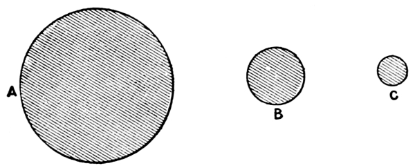
The relative economy of the supply of electricity by the use of a transformer is clearly shown by the following diagram, Fig. 7. A, B, and C give proportionately the area of cross section of the total mass [Pg 22] of copper necessary to supply 5000 16 candle-power glow lamps situated at a mean distance of 4000 feet from the dynamo. A refers to the Edison “three-wire” system, working at a potential or electrical pressure of 200 volts with a fall of potential or loss of energy in the distributing feeders of 10 per cent., average distance from dynamo 4000 feet—the usual conditions on which this system is worked. B shows the size of conductor required for the same work in an installation based on the transformer system, potential 1000 volts, allowing 2·5 per cent. loss in the supply mains—only one-fourth as much as in the direct Edison system at the same average distance from dynamo. If this loss were increased to 10 per cent., and made equal to that in the direct system, viz. 10 per cent., the size of the conductor would be that shown at C.
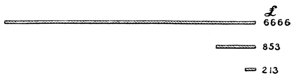
The graphic diagram, Fig. 8, demonstrates what the relative cost would be with each of the three conditions just named.
[Pg 23] Mr. Goulard’s first practical application of the secondary generator in this country was the lighting of the Underground Railway Stations, in 1883, from Edgware Road to High Street, the generating dynamo being fixed at the former place. These experiments, which were made by Mr. Kenneth Mackenzie, attracted considerable attention at the time, but it was not until the report of the jurors to the Turin International Exhibition in 1885 was published that companies were formed to instal the Goulard system for lighting an extensive district.
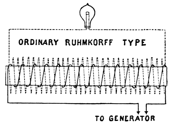
The principle underlying all transformers is that of the induction coil invented by Ruhmkorff in 1842, but described by Faraday in his “Experimental Researches,” published in 1831-2.
Fig. 9 is a diagram of the ordinary induction coil; on a central core is wound a short length of thick wire called the primary, and again over this is wound a greater length of fine insulated copper wire which forms the secondary coil. On sending a low-pressure current from the [Pg 24] generator round the thick wire, a much smaller high-tension current is induced in the secondary. A contact breaker is employed to make and break the current, or, as in the early instruments, a commutator may be used to produce the alternations. When used as a transformer the action is reversed, that is, a high-tension current is passed through the primary coil, which is composed of a wire of small sectional area, the high-pressure main connected to the dynamo also being small as compared with the distributing cable leading from the transformer, which, acting as a step-down induction coil, converts the electricity into a safe working pressure.
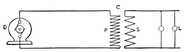
Fig. 9 a shows the arrangement of the two separate and complete circuits. D is the dynamo, P the primary coil, S the secondary, and L the lamps arranged in parallel.
It is hardly necessary to go into the technical details of the various improvements which have led up to the modern type of transformers; they are summarised by Mr. Kapp into two classes:—
No. I. are those in which the copper coils are spread over the surface of the iron core enveloping the latter more or less completely; and No. [Pg 25] II. in which the core is spread over the surface of the copper coils forming a shell over the winding.
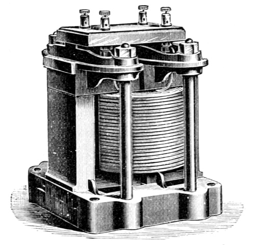
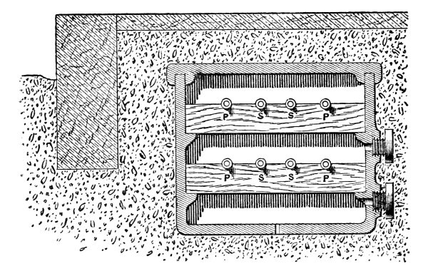
The original Goulard and Gibbs secondary generator was of the core transformer type, it had an open magnetic circuit and cores which could more or less be inserted into the coils so as to regulate the electro-motive force of the secondary circuit. The transformers were constructed with a number of copper disks or washers; these were placed alternately primary and secondary in a vertical frame, through the centre of which an iron core was fixed, consisting of a bundle of straight iron wires. The core was movable in the coil in the manner of the well-known induction coils, and thereby the electro-motive force of the secondary current could be adjusted. In their latest design the coils are circular in plan and rectangular in section and are surrounded by groups of U-shaped soft iron stampings slipped over from both sides and held together by two circular cast-iron plates with a central bolt. The magnetic lines of force pass through the core, in at one end and out at the other, and are then more or less disseminated through space; it will thus be seen that the path of the lines lies partly in iron and partly in air, and, since air has about seven hundred times more magnetic resistance than iron, it is evident that the number of lines created with a given current must be considerably smaller than would be the case if the path of the lines contained iron only. This constitutes the improvement in the Zippernowsky-Deri-Blathy system of transformer, which has coils similar to the Goulard, but with [Pg 26] the iron of the core applied in the form of a ring-shaped shell, surrounding both coils completely. This arrangement can best be described by comparing it to a Gramme armature, in which the copper and the iron have changed places. Imagine what is usually the core in an armature replaced by the primary and secondary coils, and, instead of the winding of insulated copper wire, wind iron wire around the coils, and one of these transformers is the result. In consequence of the lower magnetic resistance of the Class II. transformer, as compared to that of Class I., the electrical output obtainable with equal weights of copper and iron appears to be considerably greater in the former apparatus. Professor Feraris, of Turin, has published some of the results of comparative experiments made with Classes I. and II. and finds that the coefficient of induction is 3·6 times as great with the [Pg 27] latter as with the former. There are many varieties of transformers in the market which closely resemble each other; one of the most practical is that designed by Kapp and Snell, of which Fig. 10 is an illustration. U-shaped stampings form the shell and the cores are laid in the double trough. The cover of these troughs is formed from the metal removed from the interior of the stampings, and the whole is held together in a cast-iron frame so arranged as to allow air to circulate through the core and round the coils. The price of these transformers is about £4 per indicated horse-power, and the efficiency under the best conditions, namely, with full load, is, according to Professor Ayrton, as high as 96 per cent., and when it is doing one quarter of the full work 89 per cent.
The installation at the Grosvenor Gallery, London, may be taken to illustrate Class I. or the practical working of distribution by means of transformers.
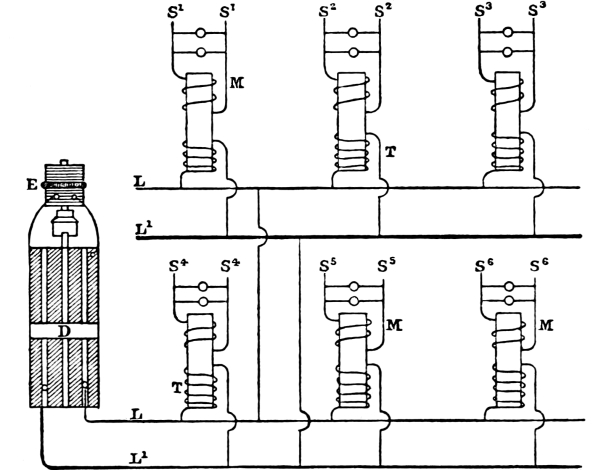
Fig. 11 represents the arrangement of primary and secondary circuits.
An alternating current is sent through the main L L¹, which is a closed circuit, and a small portion is drawn off wherever there is a secondary generator or transformer T; these instruments are placed in parallel between the conductors in the same manner as a glow lamp; neither main can be called positive or negative, as the current flows backwards and forwards many times in a second. The house wires M M [Pg 28] are joined to the secondary circuits, and are quite distinct from the main, which they do not even touch, although sufficiently near to receive an induced current alternating the same as the primary, but of a much lower electro-motive force.
| D, alternating current dynamo; | M M, secondary conductors; |
| E, continuous current dynamo for exciting; | T T, transformers; |
| L L¹, main primary conductors; | S¹ S² S³ S⁴ S⁵ S⁶, lamps in parallel. |
The Goulard transformers were used at first, but have been superseded by others designed by Mr. Ferranti; they are of the No. 2 kind, or shell type, and have a core of hoop-iron, on which the two coils are wound; the hoop-iron is then bent over, and the ends joined so as to enclose the coils. The machinery is fixed in a basement excavated under the Grosvenor Gallery; the foundations are of massive concrete, in which [Pg 29] stone supports for the engines and dynamos are embedded; the concrete does not touch the walls of the building, but a space of about 1 foot is left, which is filled in with clay; and by this simple plan all vibration of the machinery is isolated from the building. The power is obtained from two horizontal high-pressure engines, each of 600 indicated horse-power, in addition to the original two horizontal high-pressure non-condensing engines, each of 35 nominal horse-power, running at a speed of 55 revolutions per minute, which is maintained constant by means of a governor directly attached to the expansion slide-valve. The four engines drive on to a countershaft, which is cut up into lengths; each section is coupled to a dynamo and exciter by means of a conical friction-disk clutch; this permits of either length being started or stopped without interfering with the other. The speed of each engine is checked by means of a liquid speed-indicator, designed by the author. Two Ferranti alternating current dynamos, each capable of maintaining ten thousand lamps, are driven direct, one dynamo by each length of shafting: they are excited by two continuous current machines, the circuits from which are joined to a regulating apparatus, which by altering resistance keeps the electro-motive force of the large machines proportional to the number of lamps which are to be maintained. At present hand regulation is employed, but it is proposed to use automatic regulation, which will increase the life of the lamps, as they are severely tried by the variation of the current, which is more noticeable than in continuous current installations. The current from the machines is at a [Pg 30] potential of 2400 volts, and that from the transformers is 100 volts. The primary wire which carries this high electro-motive force does not enter the houses, as the transformers are, as a rule, fixed in the cellars, and from them the house branch is led in the form of a cable of fine wires, having a total diameter of 7/16 inch; the lamps, which are placed in parallel across this cable, are attached to single No. 18 or No. 20 B. W. G. wires in the usual manner. When first established, the transformers presented an element of danger, in that they, in common with all induction coils, were also condensers, and therefore a dangerous shock might be given to any one touching some unguarded portion of the lighting system. This has been prevented by the simple plan of connecting one of the terminals of every secondary circuit to earth, a method which, however, is not to be recommended, as it throws an additional strain on the insulation of the primary circuit; in fact, by earthing the secondary the insulation is practically reduced to one-half. A safety device should be inserted, which would come into operation on any leakage from primary to secondary, and immediately cut out the transformer.
The primary-current conductor is led overhead, and still remains an objectionable feature of the system, although the original trouble with the neighbouring telephones and telegraphs has been overcome. The primary circuit is a small carefully insulated cable of high conductivity copper wire, nineteen strands of No. 15 B. W. G. It weighs about 1¾ ton per mile, and is suspended, where it crosses the streets, on a steel bearer whose tensile strength is 1⅕ ton. It is so arranged [Pg 31] according to the droop of the cable that the strain of the bearer never exceeds 225 lbs., which means that the factor of safety is nearly 12 to 1. Double cut-outs or safety fuses, in many instances of the author’s design, are placed on each pole of the primary, at the point where it enters the house, so that, in the case of an excess current, the mica-foils would fuse, and all connection between that house and the supply main would cease.
Much credit is due to M. Goulard, who, in spite of great opposition to the use of his transformer system, initiated the Grosvenor Gallery installation three years ago. It has developed into not only the largest and most important central-station in Europe, but, as regards the transformer system, it supplies more lights than any in the United States. The original company has been taken over by the London Electric Supply Corporation, who are putting down plant capable of maintaining 30,000 lights, and are erecting another station at Deptford for 200,000 lights, which will be distributed by means of district transformers from mains, which it is proposed to run from Deptford through the Thames Tunnel and the Underground Railways. The electric current is supplied by meter at the price of 7¼d. per Board of Trade Unit, a price for light equal to gas at about 4s. 2d. per 1000 cubic feet.
The Eastbourne station is also on the transformer system. An alternating current dynamo, by Ellwell Parker, maintains a pressure in the primary circuit of 2000 volts, which is reduced by means of a Lowrie Hall transformer to a working pressure of 100 volts. There is a special arrangement for maintaining a constant electro-motive force in [Pg 32] the mains, independent of the number of lights in use. The mains are carried underground, and have so far given no trouble as regards the insulation of the high-tension current which passes through them. The Eastbourne company commenced by lighting the parade only with arc lamps, but now supply the incandescent light to all parts of the town, and enjoy the unique position of having obtained power from the corporation to run the mains in the streets prior to the passing of the Act of 1882. Another small station has been successfully worked for the last six years at Brighton; the group system was originally adopted, the lamps, both arc and incandescent, being placed in series or multiple series; the high-tension current is led through overhead wires in a very similar manner to the installation at Temesvar, Hungary, which is described at page 58, as an example of multiple series lighting. The extensions at Brighton are to be carried out on the transformer plan, which will necessitate the running of separate circuits, the intention of the company, however, being to gradually convert its whole system of supply to the transformer system. The Brighton Company has regularly paid dividends to its shareholders since its formation.
On the Continent the Goulard transformer is largely employed.
An important installation at Tours of 3500 lamps has been for some time successfully working. Another at Tivoli has some additional points of interest, in that the natural power of a waterfall is applied to generate electricity. Two turbines constructed by Escher Wyss, of [Pg 33] Zurich, having an available head of 29·75 feet, give 80 horse-power each, which is employed to drive two Siemens alternating current dynamos, separately excited by two small continuous current machines. Two distinct circuits of chromo-bronze naked wire, 3·7 millimetres in diameter, are run overhead, in the same manner as telegraph wires, through the town for a total length of about nineteen miles. The street lamps are fixed alternately on each circuit, so that one-half can be extinguished at a late hour without interfering with the others, or having to turn out individual lamps. The number of lamps used in the streets is two hundred glow lamps of 50 candle-power; also one hundred and twenty glow lamps of 16 candle-power for the illumination of the narrower streets. Arc lamps are also employed, as well as a large reflector lamp, the rays from which are turned on the Temples of Vesta and Sibilla. A house-to-house system is also being established, and the company which has put up the work proposes to utilise the falls of Tivoli in order to transmit 2000 horse-power for lighting purposes in Rome.
The firm of Ganz, of Budapest, who are the manufacturers of the Zippernowsky-Deri-Blathy system of transformers, have a similar installation completed in order to light a portion of Lucerne. The water power of Thorenburg 3·1 miles off, works the turbines, which drive two self-exciting alternating current dynamos of the Ganz type, similar to those shown at the Vienna Exhibition in 1884. The primary current of 38 ampères, at an electro-motive force of 1800 volts, is led [Pg 34] by four uncovered wires, each six millimetres in diameter, to the first station, which is 2·4 kilometres distant; here 1500 watts are taken off, and at 2·3 kilometres further 7000 watts are utilised in two of the hotels at Lucerne. A large installation on the same system has been put down in Rome, and several Continental cities are adopting this method of supplying electric light by small overhead wires. An advantage claimed by the Zippernowsky system is the method of keeping the strength of the magnetic field of the dynamos in accordance with the external demand for current. The regulating apparatus employed consists of a small transformer, the primary coil of which is traversed by the whole, or by a proportionate part, of the main circuit, while the secondary coil is inserted into the exciting circuit. Thus, if the main current increases, the exciting current induced in the two armature coils of the dynamo is reinforced by the inductive action of the regulating transformer; and the field of the dynamo is strengthened when more current is required. The opposite takes place when, through the extinction of lamps on the external circuit, the demand for current becomes less. In an experiment made with the transformers, which supply some five hundred electric lamps for the Teatro dal Verone and adjoining houses at Milan from the central electrical station three-quarters of a mile away, the main current was often found to vary from one ampère to thirty-five ampères; it was stated that no variation in the service pressure could be detected, and the lamps burnt with equal brightness whatever the number in use. In the experiments at the [Pg 35] Teatro dal Verone each transformer worked its own independent circuit of lamps; but, if the conditions of the different circuits were alike, they could be coupled up together in any manner desired, and thus a group of transformers could become a centre of distribution.
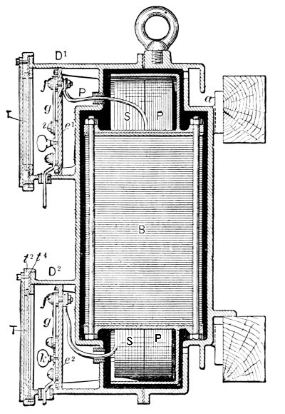
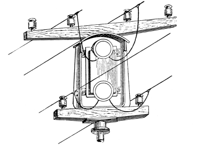
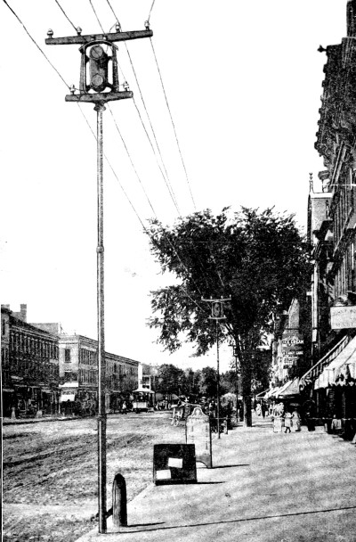
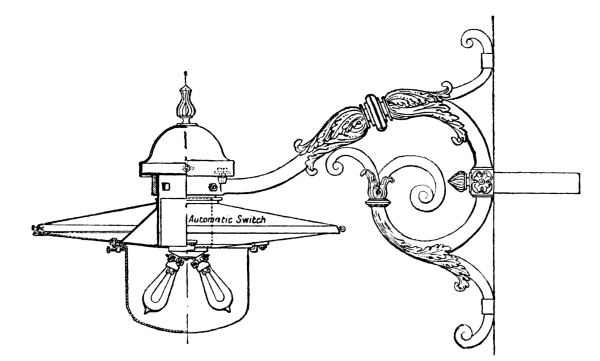
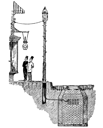
The alternating current system of the Westinghouse Company has come to the front in the United States with extraordinary rapidity, and, although it is not three years since the first plant was erected, at the present time over 190,000 incandescent lamps are operated from a number of central-stations. The fundamental principles of the Goulard system have been retained in the Westinghouse converter; but the manner in which these principles are applied has been greatly modified, while most of the details have undergone a radical change at the hands of the engineers and electricians whose researches have been utilised by the Westinghouse Company. The form of converter as now designed consists of a number of thin sheet-iron plates, shaped like the letter E, they are slipped alternately from opposite directions over the primary and secondary coils, which are disposed side by side; the inductive core is, therefore, composed of a mass of detached plates insulated from each other by paper, and forming a discontinuous magnetic circuit. In order to protect the converter from mechanical injury as well as dampness, and also to avoid the possibility of contact with wires [Pg 36] carrying currents of high potential, it is enclosed in a cast-iron case or box, made in two parts and adapted to be secured to any convenient support. Fig. 12 is a transverse vertical section of such a converter box, with the converter in position. The terminals of the primary coil, P, of the converter are led into the compartment D¹, and the terminals of the secondary coil into D². The terminals are secured to bolts or [Pg 37] couplings, f f, mounted upon insulating plates, e¹ and e². Fusible mica-foils, g, and switch plates, h and i, with plugs k, are provided for protecting and disconnecting the circuits. The open front of the compartments D¹ and D² are closed by glass plates, T, which permit inspection of the connections without entering the box. The converter box occupies little space, and may be placed in any convenient situation in or about the premises to be lighted, much the same as a gas-meter. The practice where overhead conductors are employed, is to mount the converter box on a pole in the vicinity of the premises to be lighted, as shown by Fig. 13, and thus it is only necessary to lead the secondary or low potential wires into the building, the high potential wires remaining in an accessible position upon the pole. Fig. 14 is a view of North Street, Pittsfield, [Pg 38] Massachusetts, engraved from a photograph, and shows a very neat form of tubular pole with its converter box on top. This arrangement is used throughout the city, and is a great improvement on the ordinary form of telegraph poles which so greatly disfigure American cities, and are really the most objectionable feature of the overhead wire system.
The potential ordinarily employed in the main circuits of the Westinghouse installations is about 1000 volts, and that in the lamp circuits 50 volts, the ratio of conversion, therefore, being as 20 to 1; the dynamos are manufactured, as a rule, in three sizes, No. 1 for 650, 16 candle-power lamps; Nos. 2 and 3 for respectively 1300 and 2500 lamps. The converters are also made in three ordinary sizes to supply 20, 30, and 40 lamps of 16 candle-power each. A 40-light converter contains about 85 pounds of iron and 25 pounds of copper, so that the total weight of metal is less than 3 pounds per lamp; the electrical efficiency of the converter is said to exceed 95 per cent. when the potential is reduced from 1000 volts in the primary to 50 in the secondary. “It is claimed that the trifling loss of energy in conversion from high to low potential at the point of consumption is made up for by gain at other points, especially in the increased efficiency of the lamps, so that an alternating current plant may be counted on to give 10-16 candle-power lamps per indicated horse-power, as against 7 with the direct system;” the comparative gain is doubtful, but by using 50 instead of 100 volts the life of the lamps is increased, the former having a much stronger filament and consequently a longer life. [Pg 39]
Having slightly diverged from the original lines by describing a system which is at present not introduced into Europe, a few remarks on the subject of electric motors may not be inappropriate, as they are almost universally worked in the United States, from the installation which supplies electric light. There is a considerable profit to the electric company if electric power is taken in the district, the wires conveying the lighting current are thus economically employed during the day. In the diagram, Fig. 15, which represents a district at Boston, the curve on the right principally represents the demand for power which takes place between the hours of 8 a.m. and 3 p.m. A circular was addressed to all the leading electric companies in America a short time ago, asking if they supplied power as well as light, also for what purposes it was used.
Answers were received from 56 companies, who stated that the motors were employed for:—driving ventilator fans, collar-and-cuff machines, printing-presses, various apparatus in repair-shops, sewing-machines, coffee-mills, gun-shop tools, sausage-machines, elevators, lathes, pumps, saws, ice-cream freezers, organ-bellows, and washing-machines. The size of motors varied from one-eighth to 15 horse-power; 26 companies have supplied motors from arc light circuits, 14 from arc and incandescent, and 16 from incandescent circuits alone. The motors are [Pg 40] principally owned by the subscribers, and are charged for at a rate varying from £3 to £15 per horse-power per month. The motor business is still in its infancy, but is cited to show how Electric Power can [Pg 41] supplant the steam-engine, especially for those purposes in which the power required is small and complete control is desirable.
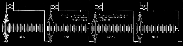
It will be found, on examining Appendix II., that in European stations by far the larger number of lamps are maintained from installations employing the Edison system; the Ferranti plan of using transformers comes next, closely followed by Goulard and Zippernowsky; the distribution with secondary batteries follows, and the high-tension multiple series comes last.
The Edison system has frequently been discussed, in connection with [Pg 42] small installations, but in magnitude the stations in Berlin and in Milan exceed anything that has been started here with continuous current.
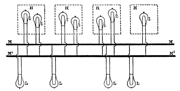
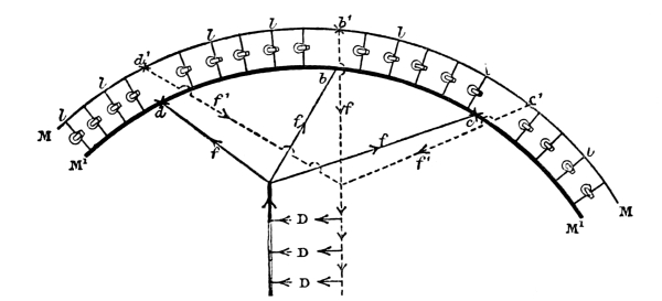
Before describing the central electric light station at the former city, it may be well to recall to mind that the Edison plan is the combination of a number of machines which pump electricity into a network of feeders, mains, and conductors, the lamps being placed in parallel circuit, as shown at L l, Fig. 16, and maintained at a constant potential of 110 volts.
M M′ are the flow and return mains, the dynamos bridging them across at one end. If the mains were very long, those near to the dynamos would be exhausting the supply, and the lamps at the remote end would not get the full pressure. A system of feeders has been devised so that each lamp, no matter where it may be, shall have approximately the full 110 volts working through it. Fig. 17 shows a long circuit consisting of two branch mains bridged by a large number of lamps, l l, and D D are [Pg 43] the dynamos at the central-station. Series of feeders, f f′, have to be taken from the dynamo mains and fed direct into the branch mains at various points, d d′, b b′, c c′, in order to distribute the electrical pressure equally.
The ordinary parallel system is undoubtedly suitable for small installations; but when the area to be lighted is extensive, it is impossible to proportion the mains, with a view to economy in the cost of copper, without sacrificing energy wasted in heating the conductors.
In Figs. 16, 17, the lamps are shown in simple parallel; but if two dynamos are connected together, and a main wire is run from each of their two extreme terminals and a third wire from the branch connecting the two machines, we have what is known as the three-wire system, which was invented by Edison in America, and Hopkinson in England, almost simultaneously. Although by using the third wire there is a saving in copper over the parallel plan, the maximum gain is not more than 25 per cent., under the best conditions; when the district to be illuminated is not more than 400 to 600 yards from the central-station, the three-wire system answers well, but as soon as this distance is exceeded the cost of the mains begins to mount up at a most alarming rate. Although there are many Edison installations in the United States on this system and a few on the Continent, it has only been used here in a few instances for factory lighting. [Pg 44]
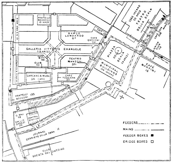
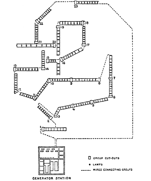
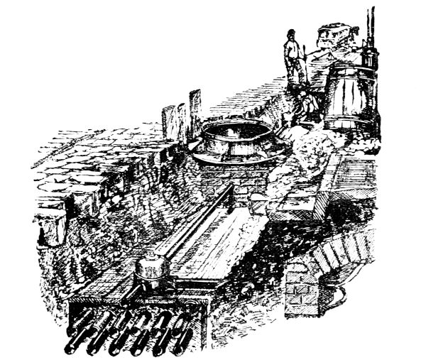
The Santa Radegonda station at Milan is at the present moment the second largest Edison station in Europe. The building, which was formerly a theatre, is well adapted for the work required; the dynamos and engines are fixed in a deep basement, while the boilers are a few feet above the street level, the upper floors being used as stores and testing-rooms. The dynamos, eight in number, are of the old Edison type, with horizontal magnets; seven of these machines are connected to the feeders which supply the mains, and these cover the district to be lighted on the Edison network system. The motive power is furnished by six Armington-Sims, and two Porter-Allen engines, each connected direct to the armature of a dynamo, the speed being maintained at the uniform rate of 350 revolutions per minute, except in the case of the spare engine and dynamo, which is kept turning slowly, ready to be switched on should occasion demand. The starting or cutting-out of circuit of these large machines requires some care. In the first place, to start, it is necessary to insert resistance into the shunt circuit of the dynamo, which is done by a switch; but to throw 150 horse-power into the main circuit would be dangerous to the lamps, so that the current is first sent into a bank of one thousand lamps used as a resistance, and these are cut out step by step; similar care is taken when a machine is stopped. To control the electro-motive force, which varies greatly from time to time, hand regulation is used during the day, with [Pg 45] the help of the Edison tell-tale, consisting of two lamps, a red and white one, which light up when the current is high or low; but when the night service comes on, as it may happen that two thousand lamps may be turned out at once, an attendant has to carefully watch the electric regulator, and be ready to insert resistance into the field-magnet circuits by moving a wheel connected by a shaft and bevel-gear to a system of commutators. The principal difficulty to be overcome, in an installation where the current is distributed over a large area, is the regulation of the electro-motive force at the various points, as at Milan; there are no return galvanometer wires, which are now used in both the two and the three-wire Edison systems in the United States. The plan devised by the company’s electrician at Milan is very ingenious, and enables the pressure at the ends of the various feeders to be kept practically the same, although they are of different lengths and sectional area. In the first place, resistance was added to each feeder to equalise the resistance in each conductor; and, in order to provide for the varying amount of current the feeder has to supply, a peculiar form of commutator, having a guillotine-shaped contact-piece, was inserted in the circuit. By moving this, suitable resistance is inserted or cut out, and the attendant, having a series of numbers, has only to set this instrument to the number shown by the ampère meter. By far the largest amount of current is drawn off for the lighting of the Scala Theatre, the stage-lighting alone taking more than one thousand lights: if these were all turned on suddenly, the other lights in the district would be dimmed; to obviate this, auxiliary feeders have been [Pg 46] run, which are used only when any great increase is expected; commutators similar to those referred to above also regulate these feeders without any special attention. The pressure at any point in the system is by this means easily controlled, and affords an illustration of what is perhaps not the most economical, but is found to be the most practicable, way of maintaining a constant potential in a district where the amount of output of current is suddenly doubled. Fig. 18 is a [Pg 47] plan of the network system of conductors laid through a large portion of the city; the conductors are in outward appearance similar to gas-pipes, the current passing through semicircular bars of copper, embedded both for the flow and return in the same iron tube, which is laid underground in a shallow trench. The house-supply is drawn from the mains, and these are connected to the feeders by means of ordinary junction-boxes, which each contain a fusible cut-out. The bridge-boxes allow of expansion of the line, and have connections for testing purposes. The insulation is extremely good, mainly on account of the favourable nature of the ground, which is chiefly gravel; no trouble has been experienced with leakage, nor has the service ever been interrupted. The cut-outs are of an improved Edison form, but have the disadvantage attending all lead plugs where the current is great, in that, to guard against accidental melting due to the heating effect of the current, the sectional area of the lead has to be much larger than would be otherwise necessary. In fact, these cut-outs will protect the cable against a bad short circuit, but nothing else.
In addition to the glow lamps, eighty arc lamps are worked in derivation, two in series; most of these lamps require 45 volts, to which 10 per cent. of idle resistance is added, constituting a total loss of current which is extremely low for a combined arc and incandescent system of lighting. The service commenced in 1882 with a little over one hundred lamps, and at present there are over ten thousand glow lamps, and two hundred arc lamps are in use. At first the [Pg 48] new enterprise had to struggle against very great difficulties; not only the technical difficulties of distribution by means of a network of feeders and mains had to be overcome, but also those arising from the prejudices of consumers and the competition of the gas company, who tried to deter consumers from introducing electric light into their houses. One of these means consisted in offering to the private consumers, resident in the district which was threatened by competition with electricity, an agreement by which the gas company bound itself to supply gas at 5s. 8½d. per 1000 cubic feet, instead of 7s. 7d. as charged hitherto; and even now those inside the “charmed circle” of the electric light conductors get their gas cheaper than the public outside. One of the reasons which accelerated the adoption of electric light was the introduction of the Edison meter, in consequence of which consumers could be charged exactly for the amount of light they had received, and were relieved from paying a lump sum according to the number of lamps fixed, which was customary in the early days of the company. The prices at which the company now provides light, at all hours of the day and night, are as under:—
| Type of Lamp. |
Installation charge per lamp. |
Charge per lamp·hour. |
|
|---|---|---|---|
| s. | d. | ||
| 10- | candle | 18 | 0·26 |
| 16- | ” | 28 | 0·40 |
| 32- | ” | 56 | 0·80 |
that is, a little over ½d. per ampère-hour; the 10-candle lamps requiring 0·5, the 16-candle lamps 0·75, and the 32-candle lamps 1·5 ampère. [Pg 49]
The company lends meters for 50, 100, and 150 lamps, at an annual rent of 4s. 10d., 7s. 3d., and 9s. 7d. respectively, and replaces, without charge to the consumer, any lamp the filament of which has broken, but it does not replace lamps where the glass is broken. For arc lamps requiring 9 to 10 ampères, an annual rent of £2 must be paid for the lamp itself, and a charge of a little over ½d. per hour for every ampère-hour. The carbons are charged for at 1d. per pair, lasting for about seven hours. Now that the installation has been in use for several years, and that the company has arrived at a very accurate estimate of the time during which an average consumer requires the light—about one thousand six hundred lamp-hours per annum—it proposes to simplify the method of charging large consumers, by omitting the initial charge of each lamp, and, instead, to charge 0·6d. for each 16-candle lamp-hour.
The Edison meters are based on the electrolytic action of a small fraction of the current which passes through the meter. They are cells, with rectangular zinc plates immersed in a solution of sulphate of zinc of 1·054 density, the distance between the plates being a little over ¼ inch. The proportion of the current which passes through the meter to that which passes directly into the consumer’s house is 1 to 973. The resistance of the shunt circuit is 9·75 ohms, made up as follows: cell, 1·75 ohm; metallic portion, 8 ohms. The resistance of the metallic portion rises with the temperature, whereas that of the cells falls with a rising temperature; and in this manner the small variations of [Pg 50] resistance which might take place in the cell are counter-balanced by the equally small variations in the resistance of the metallic portion. A complete meter consists of two similar-sized cells of the same resistance, placed in series. The object of employing two cells is, that when little current is passing, as in the summer months, one cell alone is used, and when the consumption is sufficiently large both cells are employed, and the mean between the two indications is taken as the basis for calculation in number of ampère-hours. The quantity of electricity passed through the cell is calculated by the loss of weight which has taken place in the positive plate. An employé of the society visits every meter monthly, taking away the old cells and substituting others freshly constructed. A book is kept in which the weights of the new plates and those of the returned plates are entered, and on the basis of these entries the accounts are made up. The largest plates are those in the 100-light meter, and are intended for a maximum current of 75 ampères in the main circuit; they are 6 inches long by 2 inches wide. In cases where a larger amount of current is taken, the capacity of the 100-light meter is increased by joining two or more copper strips across the terminals of the cells. The weak point of the system is the removal of the cells, which leaves the adjustment of the account to be paid entirely in the hands of the Electric-Light Company; in spite of this drawback, it is stated that there has not been a single complaint from consumers during the four years in which the meter system has been in use. [Pg 51]
It is evident that in so extensive a system of lighting a short circuit now and then between the lamp wires and the earth cannot altogether be avoided. Many of the lamps have been fitted to existing gas fittings, and are beyond the daily supervision of the company’s officers; the faulty place is often not easily accessible, so the first step taken is to discover on which of the two circuits the trouble has occurred. This is done at the station by joining two 16-candle lamps in series across the main conductors and the point of junction between the two lamps is connected to earth by a stout wire. As long as both circuits (positive and negative) are perfectly insulated from earth no current flows through this middle wire, and both lamps remain hardly incandescent; but, if one of the circuits should be in connection with the earth, the lamp which is joined on the other circuit will brighten up, because the potential of the middle wire and that of the faulty circuit are both zero, and consequently the lamp between the middle wire and the sound circuit receives the full pressure of 110 volts. To localise the fault, contact is made between the earth and the sound circuit by means of a fusible plug of known melting point, say for a thirty-lamp supply. If the fault is on a portion of the external circuit, supplying less than thirty lamps, its fusible plug will melt as soon as the sound main is put to earth. If, however, the fault is on a portion supplying more than thirty lamps, the fusible plug which has been inserted at the [Pg 52] station between the sound main and the earth will melt instead. A series of fusible plugs are thus tried, increasing in melting capacity until one is found that does not go: in this case, the other plug on the faulty portion has melted, and the consumer’s lamps on that branch are extinguished; the position of the fault is thus localised, and the company proceed to remedy the defect without interfering in the slightest degree with the rest of their system.
The Edison system is also employed at Berlin, in fact the Deutscher Edison Gesellschaft have at the present time a monopoly of the supply of the city from three large central-stations, each of which serves the area in their immediate neighbourhood. The mains differ from those used at Milan in that stranded highly insulated cables, protected with steel wire on the outside, are laid under the pavement in every street throughout the district. With the exception of the Leipziger strasse and Unter den Linden, which are lit with arc lamps suspended from chains running between cast-iron poles 24 ft. high, about 100 to 250 ft. apart, gas is used for the street lighting, and electricity for the interior illumination of many public buildings and private houses; there are also a good many arc lights outside the shops and restaurants. The mains are on the Edison network system, the area of copper being such, that when all the lamps are on there is a loss of [Pg 53] energy of 25 per cent.; but this does not occur on an average for more than half an hour a day. No sole concession is given to the company, who simply have the right to take up the pavement and cross streets, and for this permission they are bound to furnish any consumer in the district with a constant supply of electricity at the following charges:—
| 10- | candle lamps | 2·5 pf., | about | 0·29 d. | per hour. |
| 16- | ” | 4·0 | ” | 0·48 | ” |
| 32- | ” | 8·0 | ” | 0·96 | ” |
| 50- | ” | 12·5 | ” | 1·50 | ” |
| 100- | ” | 25 | ” | 3·00 | ” |
In addition to this an installation fee of 6s. per lamp is charged, which includes one lamp.
Meters are charged as follows:—
| £ | s. | d. | ||||
| 10- | to 16- | candle-power | 0 | 16 | 0 | per annum. |
| 25- | ” | 1 | 0 | 0 | ” | |
| 50- | ” | 1 | 10 | 0 | ” | |
| 100- | ” | 2 | 0 | 0 | ” | |
A discount is allowed off this meter charge, varying with the number of hours the light is used in the year.
The cost of gas is about 4s. 9d. per 1,000 cubic feet, so the electric light is slightly the dearer illuminant.
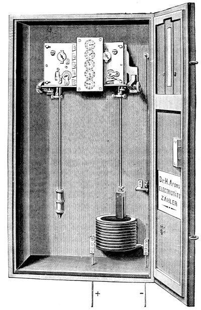
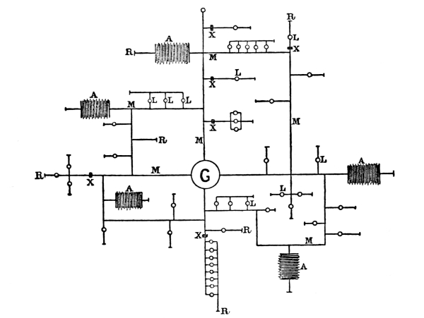
The Aron meter, Fig. 19, is usually employed as the recorder of the electricity consumed. It consists of two pendulums, controlling two distinct clockwork gears. One oscillates at a regular speed, but the other has a permanent magnet, instead of a weight, and is variable in [Pg 54] speed. The entire current passes through the solenoid, which is underneath the pendulum, with the magnet; the difference in speed [Pg 55] between the standard and variable clocks is given in direct ampère-hours by a counter-gearing similar to the index of a gas-meter. An electro-magnet starts each pendulum when the current begins to flow, and immediately it ceases, two detents come into operation and hold the pendulums stationary.
This method dates back to the introduction of the incandescent light, and, although it has been frequently demonstrated that a small current of high potential could be employed to work incandescent lamps, the series system has never been installed on a commercial scale, and is confined to arc lighting. In the United States the usual pressure for arc lighting is 2,000 volts, and it is not an uncommon occurrence to have forty arc lamps in series upon a line over 10 miles in length, carrying a current of 10 ampères. To economically use this high pressure for glow lamps in series, they must be of such design as to enable the whole of the current to be passed through them without injury. The filament of an ordinary high-resistance glow lamp would be immediately destroyed, so that low-resistance lamps, having a much larger sectional area, must be employed. The Bernstein or the Cruto lamp, which can be made to have a “hot” resistance of about 0·7 ohm, [Pg 56] and requires a current of 9·75 ampères, could be used, and the current might be economically brought from a great distance. Mr. Bernstein calculates that it would be possible to operate 6,000 of these 7-volt lamps from twenty dynamos, each giving a current of 10 ampères at a potential of 2,000 volts, and still have a margin for loss of current in the leads. An economical feature of this scheme is the easy way in which power could be saved when only comparatively few lights were required; for instance, in the daytime all the circuits could be looped together and fed by one dynamo, and, as the number of lights increased, so other machines could be switched in by having an auxiliary bank of lamps as a resistance. From the central-station twenty pairs of carefully insulated copper wires, say of No. 6 B. W. G., would lead to the houses; and, as a good-sized ordinary house takes on an average twenty lights, the conductor would pass through fifteen houses before it returned to the station. It is in the house that the practical difficulty commences, as in this series system the circuit must never be opened, so that the switches and safety appliances must be such that, whatever happens, there must remain some path for the current, otherwise all the lights on that particular circuit would be extinguished. Mr. Bernstein gives the designation of “short closed” if the current goes through the switch-lever, and “long closed” if the current is led through the lamps or other electrical devices.
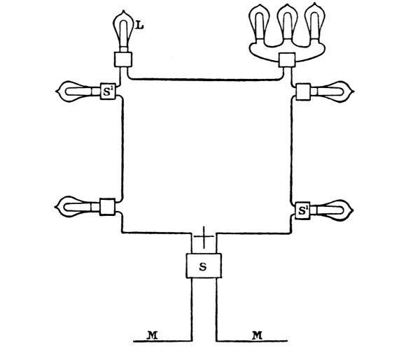
Fig. 20 is a diagram of the lamps in any building. The street main, M, [Pg 57] enters at the main switch, S, and continues from switch to switch, S¹ S¹, and returns to S before it leaves. It is necessary, to guard against any possible extinction, to construct all the switches so that it would be impossible to move the lever without a lamp was lighted; and, should the lamp give out, an equivalent resistance must be automatically inserted. These details have been investigated by Mr. Alexander Bernstein, who has designed a complete system for “series” lighting, and claims for it special economical advantages. It is, however, very doubtful if this plan can be recommended for adoption in private houses; but in public lighting, or in large establishments where an electrician could be kept to look after the fittings and the insulation of the conductors, there should be no more danger, in introducing the high-tension continuous current of 2,000 volts, than [Pg 58] there is at present with the 100-volt alternating current, and the relative saving in weight of conductors would be an important item.
Installations on this method have been erected at Messrs. Brunner and Mond’s alkali works, and in several large factories in the United States where lights had to be distributed over a considerable area; the system has not, however, come into favour for central-station work.
This method of using a high-tension current has already been referred to in connection with house-to-house lighting at Brighton, it was first employed for the street lighting of Chesterfield by the Brush Company. The electric lighting of the town of Temesvar, in Hungary, is on a far larger scale, and has, from November 1884, successfully superseded a combination of gas for the more important streets, and petroleum for the outlying ones, the total cost of which was 26,480 florins per annum. A twenty-four years’ concession was given to the International Electric Company, the plant remaining their property at the expiration of the term, subject to purchase by the municipality at their own valuation. The public lighting is stipulated to be effected by means of 731 glow lamps of the intensity of 16 candle-power; but the option is given to the company of switching out a fixed proportion of these lamps [Pg 59] at 11.30 p.m., or of leaving the whole number in operation with their light-intensity reduced from 16 to 8 candle-power from 11.30 p.m. till dawn. The total number of lighting hours per annum is 3,597½ for the lamps which are in operation from dusk until dawn, and 1,816 for those which are extinguished at 11.30 p.m. The price fixed in the concession for public lighting is 1·5 kreutzer per 16 candle-power lamp per hour, equal to 53 florins 95 kreutzers per lamp per annum of 3,597½ hours, or 27 florins 24 kreutzers per lamp per annum of 1,816 hours. The company has found it more convenient to exercise the option reserved to it, of keeping all the 731 lamps in operation from dusk till dawn, reducing their light-intensity to 8 candles after 11.30 p.m.; and the municipality has agreed to pay a round sum of 29,000 florins (£2,416 13s. 4d.) per annum for this lighting, and 41·95 florins (£3 10s.) per annum for each additional lamp worked in the same way. Comparing these figures with what precedes, it will be found that the electric lighting of the streets now in operation costs 2,520 florins more than it did on the former plan of combined lighting, partly by gas and partly by petroleum. On the other hand, the streets are lighted throughout with 16 candle-power lamps from dusk until 11.30 p.m., and with 8 candle-power lamps from 11.30 p.m. until dawn. For electric light supplied to private consumers the concession fixes the price at 1·81 kreutzers per 16 candle-power lamp per hour, or 0·1131 kreutzers per candle per hour, with the right to charge 15 per cent. more for lamps of less intensity than 16 candles. In all these prices the [Pg 60] renewal by the company of lamps failing from legitimate wear is included.
One central generating station has been provided for the whole town, from which at present four distinct circuits have been laid, each fed by a separate dynamo. The street lamps are connected up in “multiple series,” that is to say, in groups placed in series on the circuit, the lamps in each group being connected up in parallel. [Pg 61]
Fig. 21 shows the arrangement diagrammatically. Each group consists of eight lamps in parallel; at present three of the circuits have twenty-four groups in series, and the fourth circuit has twenty-three groups in series, giving a total of ninety-five groups, comprising 760 lamps, of which 731 are public lamps and 29 are used at the central station. To meet the risk of interruption in any circuit through the failure of individual lamps, an automatic switch is arranged so as to put in a reserve lamp, in the event of a whole group being interrupted. Another self-acting device will short circuit the whole group, so that the other groups in the circuit will be unaffected. The automatic lamp-switch is contained, together with the reserve lamp, in the lantern, and the automatic group cut-out consists simply of an electro-magnet with a coil of high-resistance connected up in parallel with the group of lamps it protects. These appliances have been found to work well. The main conductors are formed of insulated single copper wire, 4·6 millimetres in diameter; they are carried overhead on porcelain insulators, fixed to telegraph posts or to wooden arms let into the walls of houses; the resistance of this conductor is about 1·1 ohm per kilometre. The glow lamps are placed in reflectors at an angle of about 45° from the vertical, and are carried on brackets either fixed to the walls or on special cast-iron posts. Fig. 22 shows the details of street bracket and reflector with automatic lamp-switch and lamps in place. The brackets are for the most part fixed to the walls of houses or to painted wooden posts. [Pg 62]
The under side of the reflector, which is made of enamelled iron disposed in the form of a flat inverted cone, reflects the upward rays from the lamp and causes the extreme ones to strike the ground at a distance of about 50 metres from the foot of the lamp-post. The increase of lighting effect in the streets due to those reflectors is very marked. The upper part of the reflector serves the purpose of a case and weather protector for the automatic lamp-switch which is inserted from the top, and the lower end of which is fitted with copper hooks to which the two lamps are fixed. The glow lamps are fitted with holders of a type designed by the engineer, which provide the lamp terminals with large and strong eyes affording considerable contact surface and adapted for hooking on direct to 2·5 mm. copper wire, the ends of which have merely to be bent into a suitable form for [Pg 63] maintaining the lamp in any required position. These lamps are of an improved Lane Fox type, manufactured by the Electrical Company, at their works in Vienna. Although originally intended for 16 candle-power lamps they have so far been worked at 18 candle-power, taking 53·618 volts and about 1·183 ampères, which is equivalent to 3·522 watts per candle-power, or about 211 candles per horse-power. The current is maintained at 10 ampères, and the potential between independent groups of lamps is 53·6 volts. The aggregate energy lost, in overcoming the resistance of the main leads, switches and cut-outs, is 12·8 per cent, of the total electrical energy generated at the central-station—a very satisfactory result on a system of over 37 miles of streets. The electro-motive force in the conductors is about 1,400 volts, which is below the normal capacity of a Brush machine, thus allowing more lamps to be operated from the four machines. The machinery is driven by a 300 horse-power horizontal compound-condensing tandem steam-engine, running at the normal speed of 100 revolutions per minute. During the first 1,200 hours of lighting, only three lamps out of 760 failed, and one of these had been broken maliciously. The engineering arrangements are due to Mr. C. F. de Kierskowski Steuart, M. Inst. C.E., the various difficulties incidental to a novel work having been surmounted with experienced workmen. Although the system at Temesvar has more complicated arrangements than are now required if secondary generators are used, it has shown that it is quite practicable to light all the streets in a town by electricity; also it has enabled a comparison to be [Pg 64] made between the useful effect obtainable from arc and from glow lamps. Each group of glow lamps was found to absorb practically the same energy as one arc lamp of from 800 to 1,000 candle-power, and ninety-one or ninety-two of these could have been run with the same expenditure of power as 731 glow lamps. The eight glow lamps forming one group are in many cases scattered in different streets, often quite out of sight of each other. Under such circumstances, the substitution of one light centre, however powerful, for every eight could only be done by leaving many spots in complete darkness. To give a usefully diffused light by means of arc lamps, their number would have to be considerably greater than ninety-two, or, in other words, the standard of street lighting would have to be raised, and for this the town was not prepared to pay.
The business has now passed into the hands of the Anglo-American Corporation of London, who are extending the installation by placing alternating current dynamos at the station to work transformers for the supply of houses so as to utilise the original plant for street lighting only, as, even with the advanced knowledge of the present day, it is doubtful whether for this purpose a more economical system could be employed.
Mr. Lane Fox was the first to put forward a complete system of electrical supply on this plan, Fig. 23.
| G Generating station. | A Accumulators (secondary batteries). |
| R Returns. | M Mains or conductors. |
| L Lamps. | X Meters. |
The system is discussed by him as follows:[4]—
“The chief points of the system is the use of a generator in a central [Pg 66] position, from one pole of which insulated conductors or mains are led to the several points where the electric energy is to be utilised, being branched and sub-branched as much as required, and thence back to the other pole of the generator by an uninsulated conductor, such as the gas or water pipes. At certain points, storage or secondary batteries are set up in connection, on one hand, with the mains, sub-mains, and branches, as the exigencies of the case may require, and, on the other, with the return conductor.”
“The combination of generators, circuit and storage batteries is such, that when the current from the generators falls below the demands made on it from the various outlets to the mains at which its energy is utilised, the deficiency is made up from the storage batteries, which act in unison to supply the requisite quantity of energy. On the other hand, when the current from the generator exceeds in point of quantity the demands upon it at the various outlets, the excess goes to charge the storage batteries and to create a reserve to be called upon in case of need.”
The objection to the system which prevented it being put in practical operation was the use of the earth as a return conductor. Besides the great danger of short circuit, the gas and the water pipes, which are so thickly laid in most cities, would conduct the current and interrupt telegraphic and telephonic communication. The experiment of using storage batteries as reservoirs, from which a constant supply of electricity could be drawn as required, was tried on a considerable scale at Colchester, where a large installation was started in 1884, [Pg 67] secondary batteries being placed in favourable positions, and charged by a high-tension current. The plan adopted is shown by Fig. 24.
Fig. 24.
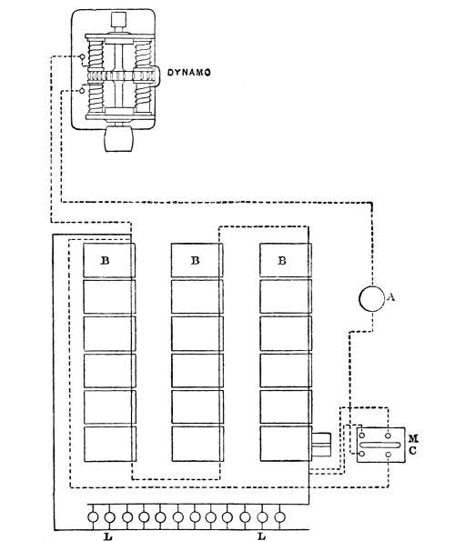
A is a meter in charging circuit;
B, the batteries or accumulators;
L, lamps in parallel on low-pressure
service main.
[Pg 68] The dynamos were two of the Brush type, each dynamo giving a current of 9·5 ampères, with an electro-motive force of 1,800 volts, when rotated at a speed of 700 revolutions per minute. They were driven by a semi-portable engine indicating 90 horse-power. The dynamos were coupled in parallel circuit for quantity, and excited by a small machine giving 10 ampères. The current was led some distance by a seven-strand 19 B. W. G. cable to the batteries, which were charged in series, the 60-volt lamps being placed in parallel on separate mains connected to the batteries. The danger of introducing a high-tension current of 1,800 volts into the houses was obviated by a rocking-switch worked automatically, so as to throw the batteries out of the charging circuit. The operation was accomplished by means of a master cell M, C, Fig. 24, similar to the others, but fitted with an arrangement to collect the gas evolved, which extended a diaphragm attached to a make-and-break arrangement which worked the rocking-switch. The Colchester installation did not turn out commercially successful, and has been abandoned; but the experiment has been valuable, and there is little doubt that, with simplification of details, a high-tension charging current could be led from a dynamo fixed in any convenient site where power is available; also in very crowded districts the batteries could be placed in cellars and be drawn from as reservoirs, so as to furnish a constant supply of electricity.
[Pg 69] The Kensington Court installation has been previously quoted as an example of what promises to be one of the most successful methods of distributing a constant supply of electricity through a large area, a description of the station may therefore be interesting. The accompanying elevation, Fig. 25,[5] shows the unpretending design of the building, and the very compact arrangement of the generating machinery and batteries. When the illustration was made the plant consisted of one Willan’s single-crank triple-expansion engine in combination with a Crompton dynamo provided with vertical inverted single magnets, the output being 250 ampères at 140 volts when running at 500 revolutions per minute, the steam pressure being 160 lbs. on the square inch. A complete duplicate plant has already been installed, and three more sets of engines and dynamos are shortly to be erected. The draught from the boiler is led downwards by an underground flue, with the object of economising the very limited space as much as possible. As a rule, the dynamo and accumulators are used in parallel, the current enters and leaves the regulating cells by the same contact, in other words, there is only one switch which serves for charging and discharging the batteries. This switch has nine contacts, so as to give nine degrees of regulation of the light; when the dynamo and accumulators are working together, the lights are parallel with either 41, 42, or 43 cells, according to the amount of charge in the cells and current required, while, when the dynamo is out of circuit, the lights are worked off, 50, 51, 52, or 53 cells. The current passes through the usual measuring instruments, and each main conductor is protected by safety fuses mounted in a Hedges duplex cut-out. [Pg 70] The accumulators are of the Planté type, but instead of being plain lead are sawn out of ingots which are cast porous on the Howell process. Each cell contains 35 plates, 8 in. × 8 in., and, as each plate when fully formed is said to be capable of yielding five ampère-hours per pound of lead, the cell has about 600 ampère-hours total capacity. In the event of a serious breakdown the whole of the work would fall on the accumulators, which could furnish a steady current for perhaps an hour or more; and herein lies the novelty of the arrangement. For the first time we have an accumulator put in not only as a fly-wheel to the whole system and to give the advantage of supplying current throughout the day and the small hours when the engine is not running, but also to act as an actual reserve. The routine is as follows:—the dynamo will start charging the accumulators a few hours before dusk; for a short time after lighting hours commence, the dynamo alone will supply sufficient current, but later on the demand will gain on the dynamo, and a certain portion of the discharge will be from the accumulators. At eleven o’clock at night the engine will be stopped and the accumulators will alone supply the demand for the rest of the night. In the small area occupied by the station there is ample room for a plant of six times the present capacity, and it is intended to erect sub-distributing stations at points at the outskirts of the district where accumulators to act as transformers will be fixed, which will be charged by a special main with a current of 500 volts, the outgoing wires from the sub-station taking electricity at the usual E.M.F pressure for incandescent lamps in houses of 100 volts. [Pg 71]
Thirteen candle lamps are used in the district, having been found to be more convenient than 16 or 20 candle-power, the 13 candle is obtained for 36 watts, or 2·75 watts per candle. The price charged to consumers is 8d. per Board of Trade unit, or equivalent to gas at about 4s. 7d. the 1,000 cubic feet. Meters on the Aron plan, Fig. 17, are used, a card being supplied on which the readings are entered exactly similar to the method adopted with gas. The service mains terminate at the meter, where the company fix for their own purposes a double pole switch of the author’s design, Fig. 26, which enables both wires to be disconnected, a spring shut-off, marked S S, prevents the switch being left partly on.
The mains from the Kensington Court Station are laid underground in a culvert 18 in. by 12 in., which is built with brickwork and cement under the pavement. A double conductor of flat copper, 0·25 square inches section, is stretched from shackle insulators attached to iron bars, which are firmly built into the culvert; the continuity of the circuit is provided by means of stranded wire, which connects each section; the flat copper rests on the top of porcelain insulators, fixed on vertical iron pieces, which are built into the floor. Connections with the sewers are left for drainage, and six surface [Pg 72] boxes are provided for every hundred yards. Where house connections have to be made, the branch wires are united by soldering to the bare copper mains. For crossing under the streets a heavily insulated cable is employed, and is led through cast-iron pipes.
Until a larger amount of mileage is actually at work, it is difficult to express an opinion as to which is the cheapest and most efficient method of laying conductors in the streets. The relative cost of two plans tried at Kensington Court—the insulated and the bare cable in a culvert—was given by Mr. Crompton in the following Tables, No. 1 and [Pg 73] No. 2, which are taken from a paper read before the Society of Telegraph Engineers and Electricians on April 12th, 1888.
Table No. 1 refers more particularly to what is known as the Callender-Webber system of using bitumen concrete, which is compressed into blocks or cases usually about 6 ft. long, 8 in. by 5½ in. section, having two-inch holes through which the insulated copper cable is led.
The estimates given in Table No. 2 were criticised by Mr. Kapp, who thought that “a more reliable conductor could be obtained by using a high-class lead-covered cable, which might be laid in the ground with the simple protection of a rough tarred plank to cover it.” The cost of digging the trench and running in the cable from the drum was quoted at 3s. a yard, and the total cost, inclusive of £10 for surface boxes, at £155 per 100 yards, instead of £187, as shown by the Table. [Pg 74]
Cost of Laying 100 Yards of Double Conductor
underneath the Footway
of a London Street.
| Single. No. 16. |
⁷⁄₁₆ | ¹⁹⁄₁₅ | ¹⁹⁄₁₂ | ¹⁹⁄₁₀ | |||||||||||
|---|---|---|---|---|---|---|---|---|---|---|---|---|---|---|---|
| Area, square inches | ·0032 | ·0225 | ·0773 | ·1613 | 0·25 | ||||||||||
| Area, square millimetres | 2·08 | 14·6 | 50 | 104 | 161·25 | ||||||||||
| Weight per 100 yards run lb. | 7½ | 53½ | 183¼ | 392 | 576 | ||||||||||
| Cost of copper at 7¾ d. | £ 0 | 4 | 10 | 1 | 14 | 6 | 5 | 18 | 0 | 12 | 13 | 0 | 18 | 15 | 0 |
| Cost of insulation | 1 | 3 | 2 | 4 | 8 | 6 | 11 | 2 | 0 | 24 | 17 | 0 | 35 | 17 | 0 |
| Total cost of Cables | 1 | 8 | 0 | 6 | 3 | 0 | 17 | 0 | 0 | 37 | 10 | 0 | 54 | 12 | 0 |
| Casing, bitumen, and cement | 5 | 3 | 0 | 5 | 5 | 0 | 8 | 0 | 0 | 12 | 10 | 0 | 12 | 10 | 0 |
| Labour, Laying | 3 | 0 | 0 | 4 | 0 | 0 | 5 | 0 | 0 | 5 | 0 | 0 | 6 | 0 | 0 |
| Trenching and repairing | 25 | 0 | 0 | 25 | 0 | 0 | 25 | 0 | 0 | 25 | 0 | 0 | 25 | 0 | 0 |
| Surface boxes and connection | 5 | 0 | 0 | 7 | 0 | 0 | 10 | 0 | 0 | 10 | 0 | 0 | 10 | 0 | 0 |
| Engineer and superintendent | 3 | 0 | 0 | 4 | 0 | 0 | 5 | 0 | 0 | 5 | 0 | 0 | 6 | 0 | 0 |
| Total | £ 42 | 11 | 0 | 51 | 8 | 0 | 70 | 0 | 0 | 95 | 0 | 0 | 114 | 2 | 0 |
| Add extra if copper, at 9½ d. | 0 | 1 | 1 | 0 | 8 | 0 | 1 | 7 | 0 | 2 | 17 | 0 | 3 | 5 | 0 |
| 42 | 12 | 1 | 51 | 16 | 0 | 71 | 7 | 0 | 97 | 17 | 0 | 117 | 7 | 0 | |
| Cost of copper per lb., laid complete | 5 | 13 | 6 | 0 | 19 | 4 | 0 | 7 | 9 | 0 | 5 | 0 | 0 | 4 | 1 |
| Current in ampères | 1·2 | 8·1 | 28 | 58 | 90 | ||||||||||
| Cost per ampère | 35 | 10 | 0 | 6 | 8 | 0 | 2 | 10 | 6 | 1 | 13 | 9 | 1 | 6 | 0 |
| ³⁷⁄₁₀ | Two Sets. ³⁷⁄₁₀ |
Four Sets. ³⁷⁄₁₀ |
Six Sets. ³⁷⁄₁₀ |
|||||||||
|---|---|---|---|---|---|---|---|---|---|---|---|---|
| Area, square inches | 0·5 | 1·0 | 2·0 | 3·0 | ||||||||
| Area, square millimetres | 322 | 645 | 1290 | 1935 | ||||||||
| Weight per 100 yards run lb. | 1153 | 2306 | 4612 | 6918 | ||||||||
| Total cost of Cables | 108 | 0 | 0 | 216 | 0 | 0 | 432 | 0 | 0 | 648 | 0 | 0 |
| Casing, bitumen, and cement | 16 | 0 | 0 | 22 | 0 | 0 | 40 | 0 | 0 | 55 | 0 | 0 |
| Labour, Laying | 10 | 0 | 0 | 18 | 0 | 0 | 35 | 0 | 0 | 50 | 0 | 0 |
| Trenching and repairing | 25 | 0 | 0 | 25 | 0 | 0 | 30 | 0 | 0 | 35 | 0 | 0 |
| Surface boxes and connection | 10 | 0 | 0 | 10 | 0 | 0 | 10 | 0 | 0 | 10 | 0 | 0 |
| Engineer and superintendent | 10 | 0 | 0 | 10 | 0 | 0 | 20 | 0 | 0 | 25 | 0 | 0 |
| Total | 179 | 0 | 0 | 301 | 0 | 0 | 567 | 0 | 0 | 823 | 0 | 0 |
| Add extra if copper, at 9½ d. | 8 | 10 | 0 | 17 | 0 | 0 | 34 | 0 | 0 | 51 | 0 | 0 |
| 187 | 10 | 0 | 318 | 0 | 0 | 601 | 0 | 0 | 874 | 0 | 0 | |
| Cost of copper per lb., laid complete | 0 | 3 | 3½ | 0 | 2 | 8¾ | 0 | 2 | 7¼ | 0 | 2 | 6¼ |
| Current in ampères | 180 | 360 | 720 | 1,080 | ||||||||
| Cost per ampère | 1 | 1 | 0 | 0 | 17 | 6 | 0 | 16 | 8 | 0 | 16 | 1 |
Cost of Laying 100 Yards of Double Conductor of
Bare Copper carried
on Insulators in a Culvert.
| Area in square inches | 0·25 | 0·5 | 1·0 | ||||||
| Area in square millimetres | 161·25 | 322·5 | 645 | ||||||
| Weight of copper in lb. per 100 yards | 576 | 1153 | 2306 | ||||||
| Cost of copper at 7¾ d. per lb. | £ 18 | 15 | 0 | 37 | 5 | 0 | 74 | 10 | 0 |
| Laying | 9 | 0 | 0 | 9 | 12 | 0 | 9 | 12 | 0 |
| Insulators | 0 | 4 | 6 | 0 | 4 | 6 | 0 | 4 | 6 |
| 6 surface boxes and connections | 10 | 0 | 0 | 10 | 0 | 0 | 10 | 0 | 0 |
| Culvert, 18 inches × 12 inches, for two lines conductor, | 53 | 8 | 0 | 53 | 8 | 0 | 53 | 8 | 0 |
| in brickwork and cement, replacing pavement | |||||||||
| Engineers and superintendence | 6 | 0 | 0 | 10 | 0 | 0 | 10 | 0 | 0 |
| Total | £ 97 | 7 | 6 | 120 | 9 | 6 | 157 | 14 | 6 |
| Extra for copper at 9½ d. per lb. | 3 | 5 | 0 | 8 | 10 | 0 | 17 | 0 | 0 |
| Total | £ 100 | 12 | 6 | 128 | 19 | 6 | 174 | 14 | 6 |
| Cost of copper per lb. laid complete | 42 d. | 27 d. | 18·2 d. | ||||||
| Current in ampères | 90 | 180 | 360 | ||||||
| Cost per ampère | 1 | 2 | 3 | 0 | 14 | 5 | 0 | 9 | 8 |
| Area, square inches | 2·0 | 2·55 | 3·00 | ||||||
| Area, square millimetres | 1290 | 1645 | 1935 | ||||||
| Weight of copper in lb. per 100 yards | 4612 | 6125 | 6918 | ||||||
| Cost of copper at 7¾ d. per lb. | 149 | 0 | 0 | 190 | 0 | 0 | 224 | 0 | 0 |
| Laying | 9 | 15 | 0 | 9 | 15 | 0 | 10 | 0 | 0 |
| Insulators | 0 | 4 | 6 | 0 | 4 | 6 | 0 | 4 | 6 |
| 6 surface boxes and connections | 10 | 0 | 0 | 10 | 0 | 0 | 10 | 0 | 0 |
| Culvert, 18 inches × 12 inches, for two lines conductor, | 53 | 8 | 0 | 53 | 8 | 0 | 53 | 8 | 0 |
| in brickwork and cement, replacing pavement | |||||||||
| Engineers and superintendence | 10 | 0 | 0 | 10 | 0 | 0 | 15 | 0 | 0 |
| Total | 232 | 7 | 6 | 263 | 7 | 6 | 312 | 12 | 6 |
| Extra for copper at 9½ d. per lb. | 34 | 0 | 0 | 43 | 10 | 0 | 51 | 0 | 0 |
| Total | 266 | 7 | 6 | 306 | 7 | 6 | 363 | 12 | 6 |
| Cost of copper per lb. laid complete | 13·8 d. | 12 d. | 12 | 6 d. | |||||
| Current in ampères | 720 | 910 | 1080 | ||||||
| Cost per ampère | 0 | 7 | 5 | 0 | 6 | 9 | 0 | 6 | 8½ |
The practical success of the Battery Transformer system has been demonstrated at Vienna, where an installation of five thousand lamps in the Opera House and Burg Theatre was maintained for the past year from a distributing station 1,400 yards away. The boilers are fixed in a basement formed by excavating the court-yard of a private house to a depth of 15 feet 6 in. below the street level; the building itself is utilised partly for offices and partly as a large dynamo and engine-room. Each dynamo is designed to give an output of 72 kilowatts or 120 ampères, at 600 volts pressure. The current is led by means of a lead-covered cable underground to the accumulators, which are erected in groups of 52 cells each, so as to give 100 volts to the lamps, with a comfortable margin. The total pressure required to charge the four groups of batteries in series varies from 430 volts at the time the batteries are giving off work, to 480 volts for the short time during which the charge is being completed. During five hours of lighting about two-thirds of the current comes direct from the dynamos; but during this time, for short periods, the demand for current often increases to such an extent that these proportions may be reversed, and the batteries supply two-thirds of the total.
The regulation of groups of batteries placed in series is not a difficult matter, and will be understood by referring to the following diagram, Fig. 27:— [Pg 77]
The four battery stations mentioned as arranged in series are represented. The current may be supposed to enter at the right hand corner, passing through the first battery with the lamps parallel to it, and from that battery to the commencement of the next, and so on through the third and fourth, the current being varied at will at the central-station, or kept constant by means of an electrical governor. The potential for each of the four groups of lamps is maintained in the following manner:—In each group one terminal is kept permanently connected to one of the discharge mains and to one of the charging mains; the other terminal can be shifted from cell to cell according to the E. M. F. required in the corresponding lamp circuit by means of a contact regulator. This movable terminal is shown by the bunch of lines [Pg 78] at one extremity of each battery group. The rule for charge and discharge is, that the terminal cell at the regulating end of the battery is so arranged that it neither receives nor gives off current, so that there is no loss of energy in the shape of E. M. F. The contact regulator, which was designed by Mr. Crompton for use at Kensington Court, is shown by Fig. 28:—
[Pg 79] The ring contacts are arranged in a line in such a manner that a circular contact-piece, made of thin sheets of copper, can be forced through them in turn by means of a central screw spindle. The mains for charge and discharge are attached to the fixed disc contacts on the central screws, and the regulating cells of the battery are coupled to their respective contact rings by sockets at the back of the board.
The difficulty with the battery transformer system is the introduction of 400 to 500 volts into the houses, which would be necessary without the batteries are always fixed in sub-stations from which a low-pressure current, say of 100 volts E. M. F., could only be distributed.
A method has been devised by Mr. Henry Edmunds to obviate this disadvantage. He also uses the high-tension current to charge the batteries, but by means of a distributor, which is automatically worked by the current, each group of cells is charged in turn, when it is entirely cut off from the supply main to the house, through which current is perhaps being taken for lighting purposes. The system is now being adopted by the Cadogan Electricity Supply Company, Chelsea.
The method of transforming by direct current without the aid of batteries is not practically at work; but, as the advantages are so [Pg 80] obvious and its development is only a question of time, a description of the system may not be considered out of place.
The electrical exhibition at Philadelphia in 1884 contained a dynamotor which was exhibited by the Van de Poele Electric-Light Company, but, as far as could be ascertained, was not worked, and, as it was simply described as an induction machine for distributing currents for the use of incandescent and other lights, it attracted little attention.
The advantages of an alternating current transformer system of distribution, Class II., has been put forward in these pages, especially that of simplicity and cheapness. An alternating current dynamo for a given output is cheaper than a direct, and it takes less labour to look after it, because it has no commutator.
An alternating transformer is also an exceedingly simple piece of apparatus. If originally made with due care and kept in a dry place, it never breaks down, as it has no moving parts, and so there is nothing to go wrong.
The alternating system of distribution has, however, some very serious disadvantages. In the first place, it is most important that motors should be driven during the day when the lights are not in use. In the second, batteries cannot be used in an alternating current system, so any immunity from breakdown that they might ensure is wanting; and steam must be kept up all day and all night.
If motors are wanted during the day, so that the load on the engine is nearly constant, batteries are not so valuable, except with a view of preventing a breakdown; but, if batteries cannot be used, the advantage [Pg 81] of using motors becomes enormous, as the plant has to be large enough to supply the maximum load, and would otherwise be idle during the day.
In alternating current systems there are two difficulties in the way of using motors. It is difficult to make an alternating current motor that will start, and, if that difficulty is surmounted, it is difficult to make an alternating current motor that will work on varying loads without great waste of power. The question of the efficiency of alternating current motors has never been really practically studied yet; and, until these difficulties are overcome, we must regard alternating current motors as non-existent. Several methods of working alternating current transformers off direct currents by commutating the primary have been proposed at different times; but they all seem to be impracticable, and it seems impossible to get over the difficulties that arise from sparking when it is attempted to break a high-tension circuit.
One of the first methods of distribution over large areas proposed was by means of motors and dynamos combined. For instance, suppose, in order to keep down the size of the leads, 2,000 volts are used in the mains, a motor capable of working with 2,000 volts is put down where the lights are wanted, and this is made to drive a dynamo giving 100 volts and a large current. Instead of having a separate motor and a dynamo connected by a belt or by coupling the spindles together, it is simpler to make one machine with two armatures, or to have only one armature with two circuits on it. One circuit is wound with fine wire [Pg 82] and takes the 2,000 volts and tends to turn the armature round. The other circuit is wound with thick wire giving 100 volts and a large current, and tends to stop the armature, thus absorbing the power supplied by the high-pressure circuit. The direct-current transformer or dynamotor is thus a sort of double dynamo, or dynamo and motor combined. If it gets 2,000 volts and 10 ampères, it would, if there were no waste, give 100 volts and 200 ampères; with a waste of 10 per cent., it will give 100 volts and 180 ampères.
In the United States it is usual to place an alternating current motor in each house to be lighted; but the conditions are quite different there, overhead wires being used extensively. In this country this system is not likely to find favour, and local sub-stations will be used, the high pressure, which is always dangerous to life, will thus be kept out of private houses and offices. There is, then, very little difference in the cost of maintenance of alternating current transformers and dynamotors, and the advantages possessed by alternating current transformers in this respect are more than counter-balanced by the use of motors on direct current circuits.
Dynamotors have not come into general use yet because no stations have been started in this country of the size which demands them. No central station with sub-stations is in operation, but there is every reason to expect several will be soon; and it is very necessary to discuss the various methods, not only in use at this moment but coming into use in the immediate future. The dynamotor itself needs no working out, as any maker of direct-current dynamos can, of course, make them. Messrs. [Pg 83] Paris and Scott of Norwich showed some in operation at the Newcastle Exhibition in 1887; the most successful type is that recently invented by Mr. Jas. Swinburne, illustrated by Fig. 29. The backward main round primary or motor magnet is shown on the left, and the forward main round the secondary or dynamo magnet on the right, the outside coil round both magnets is the shunt.
The dynamotor may be made with two circuits on one armature as already explained, or it may have two armatures in separate fields, still making up one machine. The first arrangement has two grave disadvantages. There is difficulty about securing perfect insulation between the two circuits, and this leads to chances of danger in the [Pg 84] houses. A dynamotor with two circuits on one armature cannot be compounded, that is to say, it cannot be made to give constant electrical pressure on the mains if the number of lamps is varied. A Swinburne double armature machine can be compounded, not only to give constant pressure with a varying load, but to give constant electrical pressure even if both the load and the pressure on the primary circuit vary. This makes a considerable difference in the copper of the primary leads, as in large and complicated districts it is almost impossible to arrange leads, even when working with high electrical pressure and small currents, so that the electrical pressure remains constant, or even nearly so. A very small variation of the pressure on an incandescent lamp makes an enormous difference in the amount of light it gives, and in its duration. It is, therefore, most important that the E. M. F. on the lamps should be kept absolutely constant.
This difficulty is, of course, insurmountable in the case of alternating current transformers. Alternating current transformers cannot be made to compound, and the loss in leads cannot be corrected by them, so that the lamps burn dull at full load.
If secondary batteries are used at the sub-stations, the reduction of pressure might be effected by them. A number would be charged in series and discharged in parallel. This arrangement needs at least two sets of cells, and cells are expensive; and it is difficult to preserve the insulation of cells with such electrical pressure as 2,000 volts. If cells are used for the purpose of equalising the load or as a safety reserve, it is better to charge them by means of a dynamotor. [Pg 85]
Until the balance-sheet of some large central-station has been published, it is impossible to do more than surmise what relation the earning power of the generating plant bears to the initial cost. Those central-stations which are working successfully in this country at the present time are either too small for a reliable estimate to be formed, or, as in the case of the Grosvenor Gallery, the space is too cramped for the large amount of machinery which it has been found necessary to add in order to meet the increasing demands for light. In order to obtain an approximate idea of the cost of installing a station capable of maintaining 10,000 lights, the following data (Table III.) given in Mr. Crompton’s paper before the Society of Telegraph Engineers are extremely valuable and will be examined with interest.
Although the figures given are necessarily empirical and open to criticism, the cost with both systems of distribution is approximately the same, and may be taken roughly at £5,860 per 1,000 lights, which amount, according to Professor Forbes, would be reduced to £3,914 per 1,000 lights if the installation was put down according to American practice, and at the initial cost of the Westinghouse alternating current system.
Mr. Crompton also compares the working cost of the two systems (Table IV.). [Pg 86]
Cost of 10,000-Light, or 600-Kilowatt,[6] Plant.
| A.T.—ALTERNATING TRANSFORMER DISTRIBUTION. | |
| Generating station, buildings, chimney shaft, | £ |
| water tanks, and general fittings | 11,000 |
| Dynamos and exciters—865 kilowatts, including | |
| spare sets, divided as convenient | 5,540 |
| Motive power, i.e., engines, boilers, steam and | |
| feed connections, belts, &c., at £8 12 s. per I.H.P. | 12,470 |
| 500 transformers, i.e., one to every pair of houses, at £15 each | 7,500 |
| 2,000 yards primary or charging main, exterior | |
| to area of supply, at £308 per 100 yards | 6,160 |
| 20,000 yards distributing main, 50 mm. sectional | |
| area, at £91 7 s. (see Table I.) | 14,270 |
| Regulating gear | 500 |
| £ 57,440 | |
| B.T.—ACCUMULATOR TRANSFORMER DISTRIBUTION. | |
| Generating station, buildings, chimney stack, | £ |
| water tanks, and general fittings | 8,000 |
| Dynamos—600 kilowatts, in six sets of 100 kilowatts each | 4,800 |
| Motive power, i.e., engines, boilers, steam and | |
| feed connections, &c., at £8 12 s. per I.H.P. | 8,600 |
| 4 groups of accumulators, in all 240 cells, in | |
| series, at £40 per cell, including stands | 9,600 |
| 2,000 yards charging main, at £306 17 s. 6 d. | |
| per 100 yards (see Table II.) | 6,137 |
| 20,000 yards distributing main, 161·25 mm. sectional | |
| area, at £100 12 s. 6 d. (see Table II.) | 20,125 |
| Regulating gear | 2,500 |
| £ 59,762 | |
Working Expenses and Maintenance of 10,000-Light, or 600-Kilowatt, Plant.
| Direct Alternating Transformer System. |
||||||
|---|---|---|---|---|---|---|
| Materials— | £ | s. | d. | £ | s. | d. |
| Coals: 4,380 tons at 17s. | 3,723 | 0 | 0 | |||
| ” 2,550 ”17s. | · · | |||||
| Oil, water, and petty stores: | ||||||
| 1,500 hours at 7 s. 6 d. | ||||||
| 7,250 hours at 1 s. | 925 | 0 | 0 | |||
| 1,400 hours at 5 s. | · · | |||||
| Total cost of material | 4,648 | 0 | 0 | |||
| Labour— | ||||||
| 2 foreman drivers at 45 s.; 6 drivers at 30 s.; | ||||||
| 9 firemen at 24 s.; sundry labour | ||||||
| 1 foreman driver at 45 s.; 2 drivers at 30 s.; | ||||||
| 3 firemen at 24 s.; sundry labour | 1,388 | 8 | 0 | |||
| Salaries— | ||||||
| 1 chief at £500; 2 assistants at £200 each; 4 clerks at £80 each | 1,220 | 0 | 0 | |||
| 1 chief at £500; 1 assistant at £200; 4 clerks at £80 each | · · | |||||
| 2,608 | 8 | 0 | ||||
| Maintenance of Plant— | ||||||
| Motive power and dynamos: 10 per cent. on £18,010 | 1,801 | 0 | 0 | |||
| ””10 per cent. on £13,400 | · · | |||||
| Buildings and fittings: 5 per cent. on £11,000 | 550 | 0 | 0 | |||
| ”” 5 per cent. on £8,000 | · · | |||||
| Transformers: 10 per cent. on £7,500 | 750 | 0 | 0 | |||
| Accumulators: 15 per cent. on £9,600 | · · | |||||
| Mains: 7½ per cent. on £20,430 | 1,532 | 5 | 0 | |||
| ”2½ per cent. on £26,262 | · · | |||||
| Regulating gear: 10 per cent. on £500 | 50 | 0 | 0 | |||
| ”” 10 per cent. on £2,500 | · · | |||||
| 4,683 | 5 | 0 | ||||
| 11,939 | 13 | 0 | ||||
| 2,100 units × 365 days = 766,500 units. Cost per unit | · · | 3·75 d. | ||||
| Continuous Battery Transformer System. |
||||||
|---|---|---|---|---|---|---|
| Materials— | £ | s. | d. | £ | s. | d. |
| Coals: 4,380 tons at 17s. | · · | |||||
| ” 2,550 ”17s. | 2,167 | 0 | 0 | |||
| Oil, water, and petty stores: | ||||||
| 1,500 hours at 7 s. 6 d. | ||||||
| 7,250 hours at 1 s. | · · | |||||
| 1,400 hours at 5 s. | 350 | 0 | 0 | |||
| Total cost of material | 2,517 | 0 | 0 | |||
| Labour— | ||||||
| 2 foreman drivers at 45 s.; 6 drivers at 30 s.; | ||||||
| 9 firemen at 24 s.; sundry labour | ||||||
| 1 foreman driver at 45 s.; 2 drivers at 30 s.; | ||||||
| 3 firemen at 24 s.; sundry labour | 975 | 0 | 0 | |||
| Salaries— | ||||||
| 1 chief at £500; 2 assistants at £200 each; 4 clerks at £80 each | · · | |||||
| 1 chief at £500; 1 assistant at £200; 4 clerks at £80 each | 1,020 | 0 | 0 | |||
| 1,995 | 0 | 0 | ||||
| Maintenance of Plant— | ||||||
| Motive power and dynamos: 10 per cent. on £18,010 | · · | |||||
| ””10 per cent. on £13,400 | 1,340 | 0 | 0 | |||
| Buildings and fittings: 5 per cent. on £11,000 | · · | |||||
| ”” 5 per cent. on £8,000 | 400 | 0 | 0 | |||
| Transformers: 10 per cent. on £7,500 | · · | |||||
| Accumulators: 15 per cent. on £9,600 | 1,440 | 0 | 0 | |||
| Mains: 7½ per cent. on £20,430 | · · | |||||
| ”2½ per cent. on £26,262 | 656 | 10 | 0 | |||
| Regulating gear: 10 per cent. on £500 | · · | |||||
| ”” 10 per cent. on £2,500 | 250 | 0 | 0 | |||
| 4,086 | 10 | 0 | ||||
| 8,598 | 10 | 0 | ||||
| 2,100 units × 365 days = 766,500 units. Cost per unit | · · | 2·7 d. | ||||
With the exception of the amount allowed for depreciation of the accumulators, which time alone can show to be correct, the expenses may be said to be over rather than under-estimated; the 15 per cent. depreciation given in Table IV. is under what has hitherto been found necessary to allow for the renewal of the plates of a secondary battery.
If the mean of the two results in Table IV. are taken, the working cost per Board of Trade Unit will be 3·22d., which shows that with both systems, after making due allowance for interest on capital, directors’ fees, bad debts, and other sundries omitted by Mr. Crompton, there is a probability of a very fair return on the capital expenditure, and the prospect of a handsome dividend for an electric lighting company who can sell electricity at the average price of 7d. per Unit.
The cost of maintaining and working electric lighting plant at private installations is usually much in excess of a supply from a central-station; but where the installation is over 500 lights, the difference is not very great.
The working cost at the Athenæum Club of 387 lamps for the past year is given as follows:—
| £ | s. | d. | |
| Gas for gas-engine | 446 | 7 | 10 |
| Oil”” | 71 | 3 | 8 |
| Water ”” | 35 | 0 | 0 |
| Wages | 175 | 2 | 1 |
| Sundries | 30 | 3 | 0 |
| Maintenance of lamps, etc. | 98 | 4 | 1 |
| Repairs | 103 | 1 | 1 |
| £ 959 | 1 | 9 |
[Pg 89] Average cost of lighting by gas and oil for previous years, for two-thirds number of lights £840.
At the Naval and Military Club, 420 lights cost £821 18s. for the same period, a steam-engine being used instead of a gas-engine.
The annual report of the cost of the electric light at the South Kensington Museum shows that in a larger installation, consisting both of arc and incandescent lamps, the annual cost of the latter is much less than in either of the clubs mentioned. At the Museum there are 860 16 candle-power lamps, working 655½ hours per annum, or 562,387 lamp hours; the total cost for working last year was £386, which includes £66 for repairs of engines, boilers, dynamos, and maintenance of lamps; but rent, interest on capital, depreciation of plant, and management is not included. The light is used only three evenings a week, so that the wages of the attendants are proportionately in excess of what they would be in a central-station.
The cost of arc lighting for street purposes may be estimated from the following tenders. At Taunton the local electric light company offered to extend the lighting of streets from 29 to 60 arc lamps of 1,200 candle-power nominal on the Thomson-Houston system, at the following rate:—
| Per annum. | ||||||
| £ | s. | d. | ||||
| Burning on average of | 6 hours | per night | each lamp | 17 | 7 | 6 |
| 7 | ” | ” | 18 | 12 | 6 | |
| 8 | ” | ” | 19 | 17 | 6 | |
The posts and supports to be provided and fixed by the company, or, if [Pg 90] the town council found the same, the company would allow a deduction at the rate of 5 per cent. per annum upon the outlay made by the council. The lamps are usually about 400 feet apart.
The actual cost of operating arc lights on this system is given in the following detailed expenses of a six hours’ run of a 50-light plant for the street lighting of an American city:—
| 2,600 lb. Ind. nut and slack coal, at $1·30 per ton | $1·69 |
| Engineer, one night, at $50·00 per month | 1·67 |
| Superintendent or electrician, one night, at $50·00 per month | 1·67 |
| Trimmer, one day, at $40·00 per month | 1·33 |
| 48 pairs of carbons, at $18·50 per month | 89 |
| Waste, &c., at $20·00 per year | 05 |
| Water rent, at $40·00 per year | 11 |
| Half-pint cylinder oil, at 60c. per gallon | 04 |
| One pint engine and dynamo oil, at 50c. per gallon | 06 |
| One day repairs on machine and lamps, including globes, at $120·00 per year | 33 |
| One day taxes on 50-light plant, assessed at $5,000, at 2¼ per cent. | 31 |
| One day interest on 50-light plant ($10,000), at 6 per cent. | 1·67 |
| Making a total of | $9·82 |
| 10½ d. or 20·45 cents. per lamp. £15 10 s. per annum. | |
If, in addition to the 50 street lights, 33 other arc lights are maintained, the total cost is reduced for a six hours’ run to $13·25, or £2 15s. 2d. for the 83 lights, 8d. or 15·96 cents per lamp, £12 3s. 4d. per annum.
Table V. has been calculated by M. Decker, of Nuremburg, and gives the comparative cost of working 150 lamps by electricity and by gas. The gas price (1) is that paid in Paris, namely, 6s. 9d. per 1000 cubic feet; column (2) is the price usually taken commercially, which [Pg 91] includes the fixed charges. The price of electricity is given: 1st, when a steam-engine is available; 2nd, when it is necessary to lay down a special engine; 3rd, when a gas-engine is used the gas is charged at a trifle over the price in column (1).
Total Cost per Hour and per Lamp.
| A | B | C | D | E | F | G | H |
|---|---|---|---|---|---|---|---|
| Pence. | Pence. | Pence. | Pence. | Pence. | Pence. | ||
| 500 | 1·38 | 0·485 | 1·055 | 1·216 | 0·418 | 0·552 | |
| 800 | 2·19 | 0·371 | 0·780 | 1·007 | 0·399 | 0·513 | |
| 1,200 | 3·29 | 0·314 | 0·608 | 0·865 | 0·380 | 0·352 | |
| 3,600 | 9·87 | 0·219 | 0·152 | 0·352 | 0·485 | 0·361 | 0·465 |
| Arc Lamps. | |||||||
| 500 | 1·38 | 5·235 | 4·246 | 10·459 | 11·485 | ||
| 800 | 2·19 | 3·971 | 3·089 | 7·552 | 9·272 | ||
| 1,200 | 3·29 | 3·087 | 2·441 | 6·004 | 7·581 | ||
| 3,600 | 9·87 | 2·185 | 1·510 | 3·591 | 5·586 | ||
Apart from the unsightly appearance of overhead wires, there are many reasons why any extended system of supply of electricity should be carried out by underground cables. It is true that there have been no accidents in this country due to electric light wires falling, owing to [Pg 92] the care bestowed on their insulation and erection; on account of the heat generated by the passage of the current through the leads no snow can accumulate on them, and therefore they are not subjected to the extra weight which destroyed so many of the telegraph and telephone wires in the last snow storm. Overhead electric light wires are exclusively used by the largest electric-supply company in London, and it is probable that, without further legislation takes place, other companies will shirk the expense of an underground system; and even a more dangerous method of running cables than that which has been condemned in the principal cities of the United States will become not the exception but the rule. In the city of New York the process of conversion of the present overhead to an underground system is a fact about to be accomplished to a very great extent at least, in the near future. Since July, 1887, the Western Union Telegraph Company have occupied the conduits, which have been constructed and laid with some 500 miles of wire; also the Metropolitan Telephone and Telegraph Company have 1000 miles of wire in the subways; and the Edison Illuminating Company, whose conductors were laid in the trench at the time of construction, has more than 1000 miles of underground cable. The plan adopted is to build conduits of section, as in Fig. 30, which shows the subway in course of construction, with man-hole opening and exposed ends of conduits. The single tube at top is for distribution between man-holes, and some wires are shown entering the vault on the right from the service box in the foreground. The conduits are of [Pg 93] various types; creosoted wooden tubes are placed in creosoted wooden casings; wrought-iron pipes are sometimes laid in asphaltic concrete with creosoted wooden box; another arrangement is to be of composition blocks on concrete, and cover them with brick—or wrought-iron pipe is lined with cement, and laid in hydraulic cement concrete and cased with creosoted plank. About 85 per cent. of all the conduits have been constructed on this plan, the interior diameter of the pipes being 2½ inches.
Fig. 31 shows how the street arc lighting wires are taken, also a branch for house use, out of the man-holes, which are placed at each street crossing. For the cleaning purposes and for drawing the cable [Pg 95] through the conduits, these must be laid practically straight.
Fig. 32 illustrates a method proposed by Mr. Kenneth Mackenzie, which is somewhat similar to the system of conduit which, used at Tours for the past two years, has been found most efficient for the high potential supply mains to the transformers. The troughs would be about 4 ft. long and 15 in. deep, having spigot and socket joints at the ends like ordinary water pipes. Transverse pieces of wood, or preferably slate, would rest upon projections, and would support the mains, and a cover recessed as shown would make the conduit fairly water-tight; drain holes would be provided, and the branches to houses led off through glands in the side of troughs. The American plan is, doubtless, [Pg 96] the best, as there is no space for moisture to collect in the conduits; but Mr. Mackenzie’s system is well worth trying, and has the advantage of being much cheaper in first cost.
The Edison plan is to place two solid conductors in a tube which is filled up solid with an insulating material, suitable bends and offsets being supplied, so that the tube containing the two conductors can be buried in the ground like a gas-pipe. The system is very largely used both in the United States and in Continental cities; but it is doubtful whether the protection would suffice in our towns, where the streets are already at the mercy of the gas and water companies, whose workmen, with a single blow of a pick, might perforate the tube, and cause a dangerous short circuit.
The policy of gas companies with regard to electric light has, with few exceptions, been a state of indifference to the progress of things electric, with contempt for a rival whose opposition is not sufficiently powerful to be appreciated. The chairman of a well-known gas company stated, what is undisputed,—that the introduction of electric arc lights was accompanied by an increased consumption of gas in the immediate neighbourhood where these lights are used; but it is very doubtful whether this will be the case when incandescent lights are generally supplied. The introduction of these lights into any [Pg 97] business district would mean the displacement of at least as many burners as there are electric lamps; and this reduction not only means loss of income, but also loss by interest on plant which is not kept at work to the capacity for which it was designed. The question suggests itself, “Are existing gas companies more favourably situated for furnishing electricity than any one else?” There are many reasons in favour of the supposition that the directors of gas companies have at the present time an opportunity of acquiring almost as complete a monopoly of lighting by electricity as they have with gas. As regards central-stations, everything is in their favour; there is generally some spare ground for the machinery, waste heat could be utilised, and a cheap fuel in the shape of coke is ready to hand. They have greater facilities for breaking up streets without danger of troubles arising with the local authorities, and if the Gasworks Clauses Acts, which authorise their existence, tie them down to one illuminant, a very little expenditure would enable them to enlarge their powers. In many towns the shareholders are local men who wish to use the electric light, but cannot favour its introduction because they think it would tend to smaller dividends or lower quotations for their shares; if, however, a scheme was promoted either by the gas company, or, if that was impossible, if the directors interested themselves in a separate electric light undertaking, the security which the gas and water investments command would, no doubt, cause a sufficient number of local subscribers to come forward and make even a small installation a paying [Pg 98] concern. The Imperial Continental Gas Association have already taken up the supply of electricity in Vienna, and are likely to extend this new branch of their business to the other cities in which they hold gas concessions; also in the United States the growing opposition of the electric light companies is being seriously discussed, and already several gas companies are installing electric light plants.
It is not at all probable that the scare which caused such a drop in the value of gas shares when the electric light first appeared will be repeated, but the present high price of gas shares cannot be maintained. Kerosene lamps have been for some time a far greater rival to gas than electricity. The cheapening of petroleum, which is now shipped in bulk to this country in tank steamers, will cause the consumption to increase, and enable the oil to be supplied at a price so that it can be used in petroleum-engines, and give a motive power which will be found to be far more economical than the gas-engine. The latest development of petroleum-engines is that shown by Messrs. Priestman at the Royal Agricultural Society’s Show at Nottingham. The engine in external appearance is like the Otto gas-engine, but uses the ordinary “paraffin oil” of commerce, which has a high flashing point. The oil is simply put into a closed tank, and on the top of this, air is forced which drives the petroleum into a chamber heated by the exhaust from the engine, where it is partially vaporised and led into the cylinder with sufficient air to cause it to ignite by means of an electric spark.
The report of the trials with a 5 horse-power engine show that a brake [Pg 99] horse-power was obtained for 1·7 lb. of oil, or at 6½d. per gallon for 1·4d. per horse-power per hour; with the Spiel engine the cost is stated to be 0·8d. per horse-power per hour.
Any serious reverse to the gas industry would cause a great pecuniary loss to a large number of investors. The paid-up and borrowed capital devoted to the manufacture and supply of gas in the United Kingdom exceeds £56,000,000, of which above £36,000,000 appertain to the companies and the remainder to the local authorities, whose receipts in respect of their gas undertakings last year exceeded £4,400,000.
The corporation of Bradford, who are owners of the gasworks, have wisely foreseen that it is better to keep the electric light in their own hands, and are now about to erect a central-station, and will lay underground wires; the amount sanctioned for this preliminary installation is £20,000.
A few remarks on this method of obtaining light from the combustion of crude petroleum may be added, as the light has been put forward as a cheaper and better substitute for the electric arc. The Lucigen light is produced by burning creosote oil, tar oil, or other heavy hydro-carbons, by means of compressed air in a special form of lamp, and consists of a cylinder at the side of which a steam donkey compressing pump is mounted, or in a more recent form known as the [Pg 100] Wells’ light, no separate air compressor is used, but, instead, the pressure is obtained from the water mains or from a small force pump. The cost is stated to be 3d. per hour for 2,500 candle-power, requiring three gallons of oil per hour, but is in reality at the present time double this owing to the price of the oil, which, under the most advantageous circumstances, costs on average 2d. per gallon. At the Forth Bridge these lights have been found of use in illuminating open spaces, but have not supplanted the electric arc lights which are universally employed for the lighting of the works and the interior of the shops. The disadvantages are the noise, the oil shower which pervades the vicinity of the light causing timber staging to be highly inflammable, and the difficulty of preventing water from entering the burner, a few drops sufficing to extinguish the light. The use of the Lucigen light is, therefore, very limited, and it is probable that, in situations where shadows from the arc light are found to be objectionable, large incandescent electric lamps, which are supplied up to 1,500 candle-power, would meet the case; or, failing these, petroleum could be burnt in lamps similar to those used in lighthouses with greater safety, and at not much increased cost, than the compressed-air system. [Pg 101]
To ascertain in what direction the electric current is flowing through any wire by means of a pocket compass:—
A current flowing from south to north will always deflect the needle to the west, providing the wire in which the current flows is over the instrument.
The word S. N. O. W. expresses this—south north over west; and should be remembered.
Another simple plan is to hold the outstretched right hand over the compass; then, if the current flows in the direction of the wrist to the fingers, the needle will move towards the thumb.
To find the direction of the current in the wire of an electro-magnet:
Place the palm of the hand on the coil with the fingers parallel to the wires: the thumb will point to the North Pole if the current is flowing as in previous rule towards the fingers. Conversely: if the North Pole is known, the fingers will point to the direction of the current when placed parallel with the wires, with the thumb pointing to the North Pole.
If no compass is available, take two pieces of lead and place a few inches apart in a pot containing dilute sulphuric acid, scrape the lead clean, and join a piece of wire to each and connect to poles to be tested. After current has passed a short time one piece of lead will become brown, the other grey; trace the former to the dynamo cable, and this is the positive, and should be marked with a + or be painted red for future distinction. [Pg 102]
Incandescent Lights or Glow Lights.
The number of lights required to illuminate any room would vary very much, according to the style of decoration and position of the lamps. As a rule, a similar number of glow lamps are required as there would be gas burners. The former give a much higher standard of illumination, which, curiously enough, is generally expected with electric lighting on account of the purity of the atmosphere when the full light is being used, which is not the case with gas.
One 16 candle-power lamp will light an area of about 8 feet in diameter at 8 feet above ground; in ordinary situations allow, one lamp for 38 square feet.
Arc Lighting of Works.
External.—56. 2,000 CP. arc lights will illuminate 160,000 square yards, or one for each 2,800 square yards.
Internal.—43. 2,000 CP. arc lights will illuminate 31,500 square yards, or one for each 730 square yards.
Approximate Cost of Electric Light, Museum.
| Arc lighting, | ²⁄₅ gas; | with interest, | ²⁄₃. |
| Incandescent, | ²⁄₃ gas; | with interest, | ⁴⁄₃. |
Motive Power.
Compound engine 2 lbs. of coal per indicated horse-power per hour.
Good single-acting engine 3 to 6 per indicated horse-power per hour.
An indicated horse-power can be obtained in a compound engine from 20 lbs. of steam per hour.
A good boiler evaporates 9 to 10 lbs. of water per lb. of coal.
From 21 to 28 cubic feet of gas are required in a gas-engine per indicated horse-power per hour.
Incandescent Lamps.
In practice allow 9-60 watt 16 CP. lamps per indicated horse-power of engine.
Mem. for Wire Running.
Leads to the left or “low,” “light coloured.”
Returns to the right or “raised,” “red.”
English and French Measures.
| Millimetre | = | 0·039 | inches | 1 mill | = | ·0254 | millimetres. |
| Centimetre | = | 0·393 | ” | 1 inch | = | 2·5399 | centimetres. |
| Decimetre | = | 3·93 | ” | 1 foot | = | 3·3480 | decimetres. |
| Metre | = | 39·37 | ” | 1 yard | = | ·91439 | metres. |
| Cubic metre | = | 35·32 cubic feet or 1·31 cubic yards. | |||||
The Paris Congress Units (1884) are now universally adopted and consist as follows:
Electro-motive Force, and Potential (E).—The Volt. The legal volt is ·926 of the E. M. F. of a Daniell’s cell, which for rough purposes may be taken as a volt.
Resistance (R).—The Ohm. The legal ohm is now represented by the resistance of a column of mercury of a square millimetre in section at the temperature of zero centigrade 1·062 metres long.
Current (C).—The Ampère. This is the strength of current sent through a wire having the resistance of 1 ohm at the E. M. F. of 1 volt.
Quantity (Q).—The Coulomb. It is the quantity of electricity given by an ampère in a second. One coulomb decomposes ·00142 grain of water.
Heat or Work (W).—The Joule, or Volt-Coulomb, is the work done by 1 coulomb in 1 ohm. The work done by any current per second is obtained in ergs by the product of the current into the electro-motive force producing it or W = CE or W = C²R. The Erg is the C. G. S. unit of work.
Power (P).—The Watt, 1 ÷ 746 of a horse-power, employed in doing 1 joule of work in 1 second.
HP, or the Horse-power, is found by dividing C E by 746, thus (CE)⁄₇₄₆ or (C²R)⁄₇₄₆ = HP.
See also explanation of terms.
ELECTRICAL TABLE OF THE BIRMINGHAM WIRE GAUGE
FOR PURE COPPER.
| B.W.G. No. |
Diameter in Inches. |
Diameter in Millimeters. |
Area in Square Inches. |
Circumference in Inches. |
Pounds per Mile. |
Feet per Pound |
Feet per Ohm. |
Ohms per 1000 Feet. |
|---|---|---|---|---|---|---|---|---|
| 1 | ·3 | 7·62 | ·070686 | ·94248 | 1444·0087 | 3·662 | 8706·843 | ·1148 |
| 2 | ·284 | 7·21 | ·063347 | ·89221 | 1291·8699 | 4·0988 | 7803·51 | ·1282 |
| 3 | ·259 | 6·58 | ·052685 | ·81367 | 1074·5697 | 4·9262 | 6490·09 | ·1540 |
| 4 | ·238 | 6·04 | ·044488 | ·74770 | 907·3683 | 5·850 | 5580·01 | ·17007 |
| 5 | ·22 | 5·59 | ·038013 | ·69115 | 773·045 | 6·83 | 4681·1 | ·2136 |
| 6 | ·203 | 5·16 | ·032365 | ·63774 | 657·205 | 8·02 | 3985·7 | ·2509 |
| 7 | ·180 | 4·57 | ·025447 | ·56549 | 517·493 | 10·20 | 3134·8 | ·3190 |
| 8 | ·165 | 4·19 | ·021382 | ·51836 | 434·861 | 12·14 | 2633·7 | ·3797 |
| 9 | ·148 | 3·76 | ·017203 | ·46495 | 349·853 | 15·10 | 2119·9 | ·4719 |
| 10 | ·134 | 3·40 | ·014103 | ·42097 | 286·651 | 18·44 | 1737·0 | ·5757 |
| 11 | ·120 | 3·05 | ·011309 | ·37699 | 229·997 | 22·95 | 1392·9 | ·7179 |
| 12 | ·109 | 2·77 | ·009331 | ·34243 | 189·763 | 27·82 | 1149·4 | ·8700 |
| 13 | ·095 | 2·41 | ·007088 | ·29845 | 144·144 | 36·63 | 873·1 | 1·1454 |
| 14 | ·083 | 2·11 | ·005411 | ·26075 | 110·035 | 47·98 | 665·3 | 1·503 |
| 15 | ·072 | 1·83 | ·004071 | ·22619 | 82·790 | 63·77 | 501·5 | 1·9941 |
| 16 | ·065 | 1·65 | ·003318 | ·20420 | 67·478 | 78·25 | 408·7 | 2·4466 |
| 17 | ·058 | 1·47 | ·002642 | ·18221 | 51·3163 | 102·89 | 310·8 | 3·2176 |
| 18 | ·049 | 1·24 | ·001886 | ·15394 | 38·3486 | 137·68 | 232·3 | 4·3052 |
| 19 | ·042 | 1·07 | ·001385 | ·13195 | 28·1741 | 187·40 | 170·6 | 5·8599 |
| 20 | ·035 | ·89 | ·000962 | ·10995 | 19·5677 | 269·83 | 118·5 | 8·4381 |
| 21 | ·032 | ·81 | ·000804 | ·10053 | 16·3574 | 322·79 | 99·1 | 10·094 |
| 22 | ·028 | ·71 | ·000616 | ·08796 | 12·5242 | 421·58 | 75·8 | 13·185 |
| 23 | ·025 | ·63 | ·000491 | ·07854 | 9·9845 | 528·82 | 60·5 | 16·539 |
| 24 | ·022 | ·55 | ·000380 | ·06911 | 7·7299 | 683·06 | 46·8 | 21·357 |
ELECTRICAL RESISTANCE OF COPPER WIRE
IN FRENCH MEASUREMENTS.
| B.W.G. No. |
Diameter in Millimetres. |
Area in Millimetres. |
Circumference in Millimetres. |
Metres per Kilogramme. |
Kilogrammes per Metre. |
|---|---|---|---|---|---|
| 1 | 7.62 | 45.6 | 23.9 | 1ᵐ.95 | 0ᵏ.514 |
| 2 | 7.21 | 40.8 | 22.6 | 2.78 | 0.360 |
| 3 | 6.58 | 34 | 20.7 | 3.33 | 0.300 |
| 4 | 6.04 | 28.7 | 19 | 3.95 | 0.253 |
| 5 | 5.59 | 24.5 | 17.6 | 4.61 | 0.217 |
| 6 | 5.16 | 21 | 16.2 | 5.43 | 0.184 |
| 7 | 4.57 | 16.4 | 14.3 | 6.90 | 0.145 |
| 8 | 4.19 | 13.8 | 13.1 | 8.20 | 0.122 |
| 9 | 3.76 | 11.1 | 11.8 | 10.20 | 0.098 |
| 10 | 3.40 | 9.1 | 10.7 | 12.50 | 0.080 |
| 11 | 3.05 | 7.3 | 9.6 | 13.50 | 0.074 |
| 12 | 2.77 | 6 | 8.7 | 18.87 | 0.053 |
| 13 | 2.41 | 4.6 | 7.6 | 24.80 | 0.0403 |
| 14 | 2.11 | 3.5 | 6.63 | 32.40 | 0.0309 |
| 15 | 1.83 | 2.63 | 5.75 | 45.10 | 0.0232 |
| 16 | 1.65 | 2.14 | 5.18 | 52.90 | 0.0189 |
| 17 | 1.47 | 1.70 | 4.62 | 69.40 | 0.0144 |
| 18 | 1.24 | 1.21 | 3.90 | 94.30 | 0.0106 |
| 19 | 1.07 | 0.9 | 3.36 | 135.10 | 0.0074 |
| 20 | 0.89 | 0.62 | 2.80 | 181.8 | 0.0055 |
| 21 | 0.81 | 0.51 | 2.54 | 212.8 | 0.0047 |
| 22 | 0.71 | 0.39 | 2.23 | 285.7 | 0.0035 |
| 23 | 0.63 | 0.31 | 1.98 | 364 | 0.0028 |
| 24 | 0.55 | 0.24 | 1.73 | 465 | 0.00215 |
| B.W.G. No. |
Resistance in Ohms | Kilogrammes per Ohm. |
Metres per Ohm. |
|
|---|---|---|---|---|
| per Kilogramme. | per Metre. | |||
| 1 | 0.00073515 | 0.0003777 | 1360 | 2652 |
| 2 | 0.00116760 | 0.000420 | 860 | 2379 |
| 3 | 0.00168165 | 0.000505 | 595 | 1980 |
| 4 | 0.00232260 | 0.000588 | 430 | 1700 |
| 5 | 0.03227000 | 0.000700 | 310 | 1430 |
| 6 | 0.00452319 | 0.000833 | 220 | 1200 |
| 7 | 0.00731400 | 0.00106 | 137 | 945 |
| 8 | 0.01025000 | 0.00125 | 98 | 802 |
| 9 | 0.01581000 | 0.00155 | 63 | 646 |
| 10 | 0.0237500 | 0.00190 | 42.20 | 527 |
| 11 | 0.0318600 | 0.00236 | 31.40 | 424 |
| 12 | 0.0539682 | 0.00286 | 18.60 | 350 |
| 13 | 0.0932480 | 0.00376 | 19.70 | 266 |
| 14 | 0.160380 | 0.00495 | 6.26 | 202 |
| 15 | 0.294954 | 0.00654 | 3.40 | 153 |
| 16 | 0.430077 | 0.00813 | 2.30 | 123 |
| 17 | 0.73564 | 0.0106 | 1.35 | 94.5 |
| 18 | 1.33906 | 0.0142 | 0.75 | 70.4 |
| 19 | 2.60743 | 0.0193 | 0.38 | 51.9 |
| 20 | 5.05404 | 0.0278 | 0.20 | 36 |
| 21 | 7.04368 | 0.0331 | 0.14 | 30.2 |
| 22 | 12.37081 | 0.0433 | 0.08 | 23.1 |
| 23 | 19.6924 | 0.0541 | 0.05 | 18.5 |
| 24 | 32.5500 | 0.0700 | 0.03 | 14.3 |
For Table of English Measurements see page 105.
Accumulator.—Another name for secondary batteries.
Alternate Current Dynamo.—Produces currents which are alternately positive and negative.
Amalgamation.—Zinc is protected from local action by having its surface coated with mercury.
Ampère.—The Unit of current. A volt divided by an ohm.
(See Electrical Measurements, page 104.)
Ampère Meter.—An instrument used for measuring strength of current.
Anode.—The positive electrode or pole of a decomposing cell, the wire or plate connected to the copper or other negative element of a battery. In electro-plating, it is usually the soluble pole of the metal to be deposited. (v. Cathode.)
Arc.—The air space in which the electric light forms.
Armature.—The keeper of a magnet: the part which closes the magnetic lines of the field-magnet, or the rotary part.
Battery.—A combination of two or more voltaic cells coupled together.
B. A.—British Association.
Block Station.—A central-station for the supply of continuous buildings.
Board of Trade Unit.—One thousand watt hours equals 10 ampères at 100 volts per hour, or 1·35 HP. working for one hour.
Bobbin.—A coil of wire, or a number of such coils, generally [Pg 108] so mounted that they can be rapidly revolved.
Bridge (Wheatstone’s).—An apparatus for measuring resistances by balancing the unknown resistance against one known and capable of adjustment.
B. W. G.—Birmingham wire gauge.
Candle-Power.—Term used to denote the amount of light as compared with a standard sperm candle, which is a spermaceti candle, burning at the rate of 2 grains per minute.
Carbons.—The electrodes of arc lamps; the negative plate of a battery.
Carcel Lamp.—The French standard, equal to 9·4 candles.
Capacity (K).—The powder of a surface to hold electricity as “static charge.” A coulomb divided by a volt. Its Unit is the Farad.
Cathode.—The negative pole of a battery; the wire or plate connected with the zinc or positive element of the battery. The object on which a metallic deposit is to be formed. (v. Anode).
Centimetre.—The hundredth part of a metre.
Cell.—Each separate vessel in which a chemical action occurs, by which electricity is capable of being developed.
Central-station.—A building containing plant for supplying electricity to the public.
C. G. S.—The centimetre-gramme-second system.
Circuit Conductive.—The wires which form the path for the passage of the current.
Commutator.—A circuit changer, or switch. The collector of currents on a dynamo.
Compound Winding.—A method of increasing or decreasing the [Pg 109] energy developed in a dynamo in proportion to the demand.
Conductivity.—Is the reciprocal to resistance, and applies to that property of any substance whereby the passage of electricity through it is effected with the least opposition.
Conductors.—Substances which most freely permit electricity to pass.
Connections.—Wires, &c., completing the circuit between different apparatus.
Contact Breaker.—The electric lighting equivalent for a gas tap.
Coulomb (Q).—The Unit of quantity, which passes in one second of an ampère current.
Cut-out.—An instrument placed in the circuit which will open it automatically.
Current (C).—The Unit is the Ampère. The supposed flow or passage of electricity or electrical force in the direction from + to -, or positive to negative.
Current Reverse.—A current in the opposite direction to the normal current.
Decimetre.—The tenth part of a metre.
Deflection.—The angle or number of degrees through which the needle of a galvanometer moves when a current is passing through its coils.
Diaphragm.—A porous division between two liquids through which electric current passes.
Duplex Cut-out.—An instrument which enables a spare fuse to be immediately substituted for that melted. [Pg 110]
Duty.—A term used to denote the economy of any motor.
Dynamo.—A name given to machines which produce electricity for commercial purposes.
Dynamometer.—An instrument for ascertaining the horse-power absorbed by any machine.
Dyne.—The Unit of force which gives a velocity of 1 centimetre per second to 1 gramme weight after acting for 1 second.
Direct-Current Dynamo.—An electric generator producing currents passing in one direction.
Earth.—A term for the return circuit, which for economy is formed through the earth in telegraph work. A return conductor common to many circuits is sometimes called “earth.”
Electrodes.—A term for the poles or plates leading the current into and out of a cell.
Electrolysis.—The act of decomposition by the electric current.
Electrolyte.—The liquid in a cell.
Electrometer.—An instrument for measuring electric potential.
Electro-motive Force (E. M. F.) (E).—The electric force tending to produce electric current. The Unit is the volt.
Erg.—The C. G. S. Unit of energy. The work of moving a body through 1 centimetre against the force of a dyne.
Extra Current.—The induced current of higher E. M. F., which appears in a wire wound in a helix when the current is broken.
Farad.—The Unit of capacity: a coulomb divided by a volt.
Field of Force.—The space between or around the poles of a magnet. [Pg 111]
Filament.—That part of an incandescent lamp which gives out the light.
Field-Magnets.—In a dynamo the magnets between which the armature revolves.
Foot Pound.—The British Unit of work, or 1 lb. raised 1 foot high.
Galvanometer.—An instrument for measuring current.
Generator.—Another term for a dynamo.
Governor.—An apparatus for controlling the speed of any motor.
Horse-Power (HP.)—indicated HP.—The Unit is 33,000 lbs. lifted 1 foot high per minute. The nominal HP. of any motor is generally fixed considerably less than the indicated.
| Ind. HP. of any engine = | 2(A P R S) |
| 33,000 |
| A = | Area of piston in square inches. |
| P = | Average pressure of steam in lbs. per square inch. |
| R = | Number of revolutions per minute. |
| S = | Length of stroke in feet (if in inches, × 33,000 by 12). |
The French “force cheval” represents 32,560 foot pounds.
Horse-Power of Water.—Indian Government rule, 15 cube feet per second falling through 1 foot = 1 HP.
Indicator Diagram.—The drawing produced by an instrument which is fixed to the cylinder of a steam-engine for the purpose of ascertaining its duty. [Pg 112]
Induction.—The name given to effects produced out of a force-exerting body or out of the circuit to which the force is directly applied. A current in a wire induces currents in other conductors parallel to it.
Inertia.—The resistance to change of state of rest or motion.
Insulators.—Bodies possessing high electrical resistance. All insulating substances, however, allow some electricity to pass.
Intensity.—The old term for the properties now described as E. M. F. and potential.
Joule, also called Joulad (W).—The Unit of heat or work, it has also been applied to the mechanical equivalent of heat, 772 foot lbs.
Kilowatt.—One thousand watts.
Knot.—The geographical and nautical mile.
Leads.—Terms usually applied to copper conductors.
Magnetism.—A condition which can be highly developed in iron and steel, by electric action or otherwise.
Measurement.—See Units.
Metre.—The French standard of length = 3·28 feet.
Meg Ohm.—The prefix meg signifies a million.
Millimetre.—The thousandth part of a metre.
Milliampère.—The thousandth of an ampère.
Mica-foil.—The fusible portion of a Hedges cut-out.
Multiple Arc.—Galvanic cells or dynamos connected parallel, or lamps so arranged that each furnishes a separate path for the current. [Pg 113]
Negative.—In a machine the wire returning from the lamp. In a galvanic battery the copper, carbon, or platinum plate. Sign -.
Nigger.—An American term used to denote an electrical fault.
Ohm.—The Unit of resistance. A volt divided by an ampère.
Ohm’s Laws.—Laws, investigated by Ohm, regulating electrical current magnitudes. Calling the current C, electro-motive force E, and resistance R: the expression is
| Current | E. M. F. | Resistance. |
|---|---|---|
| C = E ⁄ R, amps. | E = C × R, volts. | R = E ⁄ C, ohms. |
| (See Electrical Measurements.) | ||
Osmose.—The process of diffusion of liquids through a porous division.
Paraffin.—An insulating substance much used in telegraphic work.
Plummer Block.—The bearing on which a shaft revolves.
Polarity.—The distinct features of the two separate poles of a magnet.
Poles.—The two ends of a magnet. The wires, plates, &c., leading from a battery.
Positive.—In a machine the wire proceeding to the lamp. In a battery the zinc plate. Sign +.
Potential.—A word used to indicate a condition for work. Difference of potential is a difference of electrical condition. [Pg 114] Potential of a battery means its E. M. F.
Power (P).—The rate of doing work. When an ampère passes through an ohm, the unit power, called a watt, is required.
Quantity (Q).—The Unit is the Coulomb.
Relay.—An electro-magnet which, receiving its current from a distance, closes the circuit of a local battery so as to produce the required effect of strength.
Resistance (R).—The opposition presented by the circuit to the development of the current. The Unit of resistance is the Ohm.
Rheostat.—An instrument for inserting resistances. A valuable artificial resistance employed for measuring unknown resistances.
Return Current.—The current in the wire leading to the machine.
Rigger.—The pulley or wheel by which power is transmitted.
Secondary Battery.—Wrongly termed an accumulator, is an appliance for storing energy in such a form that it shall be available for the reproduction of electric currents.
Secondary Generator.—A transformer of a current of high potential into a current of less E. M. F.
Series.—The plan of connecting lamps so that the current passes one after the other.
Shunt.—A coil of wire arranged to take a certain proportion of any current.
Solenoids.—Helices of wire which act like magnets.
Switch.—An apparatus for changing one circuit on to another. [Pg 115]
Spectrum.—The elongated figure of the prismatic colours.
Torque.—Term used to express the strain on a shaft due to electro-magnetic action.
Units.—The various bases of any system of measurement.
Volt.—The Unit of electro-motive force and potential. An ampère multiplied by an ohm. (See Electrical Measurements.)
Voltameter.—An apparatus for measuring the current by its chemical action.
Voltmeter.—An instrument used for measuring E. M. F.
Watt.—The Unit of power. A volt-ampère. The horse-power electrical, taken as 746 B A watts, is equivalent to only 736 true watts. The horse-power electrical is equal to 756 B A watts, which is equal to 746 true watts. The “force de cheval,” or horse-power in use abroad, is defined as 75 kilogrammetres, and is, therefore, 736 true watts.
Work (W.)—Is a volt multiplied by a coulomb, or (amp.² × sec × ohm) or (amp. × sec × volt). The Unit is the Joule.
Yoke.—Is a term applied to the apparently neutral mass of iron which connects the poles of a horse-shoe magnet at the back.
| Name of Station. |
Approximate No. of Lights. |
Systems employed. |
Approximate length of longest main supply conductor in miles. |
Main conductor overhead or underground. |
|
|---|---|---|---|---|---|
| Incandescent or Glow Lamps. |
Arc. | ||||
| Brighton Electric- Light Company | 1,800 | 40 | High-tension lamps in multiple series Brush Dynamos |
20 | Overhead |
| Cadogan Electricity Supply Company (New Company) | · · | · · | Edmunds’ system of Battery Transformers |
2 | Overhead |
| Eastbourne | 1,700 | 30 | Lowrie Hall Transformers |
15 | 7 miles underground |
| Grosvenor District Electrical Supply | 20,000 | 40 | High-ension with Ferranti Transformers primary 2,400 volts, secondary 200 volts, Ferranti dynamos |
6 circuits, total about 70 miles | Overhead |
| Kensington Court Electric Lighting Company |
1600 to be extended to 10,000 |
· · | Crompton 105 volts low tension, constant supply by means of accumulators |
¼ | Underground |
| Liverpool | 1,000 | · · | Low tension continuous current dynamos | · · | Overhead and Underground |
| Leamington | 1,500 | · · | Chamberlain and Hookham dynamos with accumulators |
1¼ | Underground |
| Paddington Electric Lighting | 4,115 16 C. P. lamps |
98 3,000 C. P. |
E. M. F. 150 volts, Gordon alternating current Dynamos |
3 | Underground |
| Barnet and District E. Supply Company (New Company) |
· · | · · | Joel Dynamos | 5 | Overhead chiefly |
| Chelsea E. Supply Company (New Company) | · · | · · | · · | · · | · · |
| St. James and Pall Mall (New Company) | · · | · · | Continuous current |
· · | · · |
| Taunton | · · | 23 | Thompson Houston continuous current |
· · | Overhead |
| Whitehall Court (New Company) | · · | · · | Battery Transformer system |
· · | · · |
| Westminster | · · | · · | · · | · · | · · |
| West Brompton | · · | · · | Lowrie Hall Transformers |
10 miles when completed | · · |
| Adelphi Theatre | 4,000 | · · | Continuous current dynamos coupled direct to engines |
12 external circuits | Overhead and Underground |
| Bath (New Company) | · · | 85 | Thomson Houston Dynamos and Transformers |
· · | · · |
| Name of Station. |
Approximate area of distribution. |
Working Capital. |
Hours of Supply. |
Charges. | Remarks. | |
|---|---|---|---|---|---|---|
| By Meter. | By yearly fixed amount. |
|||||
| Brighton Electric- Light Company |
About 3 square miles |
£12,000 | Constant | Meter rent 21 s. 8 d. per annum |
Glow lamps, 1 s. per unit, or rather over ¾ d. per lamp per hour. Arc lamps, 4 s. per lamp per week including maintenance |
If consumption is below 100 units quarterly, 10¾ d. discount. |
| Cadogan Electricity Supply Company (New Company) |
Belgravia and Cadogan Estate |
£20,000 | · · | · · | · · | · · |
| Eastbourne | · · | £20,000 | Constant | · · | According to consumption averaging about 6½ d. |
A similar station at Hastings. |
| Grosvenor District Electrical Supply |
Very irregular district, a house is lighted 2 miles from the station |
£375,000 | 8 a.m. to 3 a.m. |
7½ per Board of Trade unit |
· · | A station at Deptford is under erection to maintain 200,000 lights. |
| Kensington Court Electric Lighting Company |
The streets adjoining the station, the mains to be continued to another station at Knightsbridge |
£25,000 | Constant | By meter and minimum charge of 10 s. per annum |
8 d. per unit, equal to 0·56 d. per 20 C.-P. lamp per hour, or 0·28 d. per 10 C.-P. lamp. Shops taken at £2 per annum per 20 C.-P. lamp minimum of 10 lights |
District embraces residences, shops, public hall, and church. |
| Liverpool | · · | £20,000 | · · | By meter on sliding scale |
First 400 hours, 1 s. per unit Second ” ” 8 d. ” Afterwards4 d. ” |
Board of Trade license for six years, hotels, shops, and residences. |
| Leamington | 183 street lamps |
· · | Constant | meter | Street lights £2 2 s. per annum for 2,860 hours, including renewals. 1 to 40 units per quarter 8 d. per unit. 41 to 150 units per quarter, 6 d. per unit. 151 units per quarter 4 d. per unit |
· · |
| Paddington Electric Lighting |
67 acres | · · | Constant | · ·[Pg 118] | Worked by G. W. Railway |
The district between Paddington and Westbourne Park is lighted throughout. |
| Barnet and District E. Supply Company (New Company) |
· · | £5,000 | · · | · · | · · | 71 lamps in streets on posts 12 ft. high. |
| Chelsea E. Supply Company (New Company) |
· · | · · | · · | · · | · · | · · |
| St. James and Pall Mall (New Company) |
· · | · · | £20,000 | · · | · · | Area to be lighted adjoining station. |
| Taunton | Street lighting | · · | · · | · · | By yearly contract | Arc lamps of 1200-C.-P. |
| Whitehall Court (New Company) |
To light hotels in Northumberland Avenue |
£24,753 | Constant | Proposed meter-rent 10 s. per quarter |
Proposed charge, 8 d. per unit with minimum of £1. 1 per lamp per annum |
Amalgamated with the Metropolitan Electric Supply Company. |
| Westminster | · · | · · | · · | · · | · · | New Company. |
| West Brompton |
· · | · · | Constant | By meter | The station is being erected by the House to House Lighting Company, who also propose installations in other districts. |
|
| Adelphi Theatre |
The buildings are close together |
Private | · · | · · | The Adelphi Theatre, Adelaide Gallery, and Strand Restaurant are lit, the machinery being fixed in a basement about 30 × 45 feet. No gas is laid on. |
|
| Bath (New Company) |
Arc lights |
· · | · · | · · | Yearly contract | The power obtained from town weir supplemented by steam-engine. |
| Name of Station. |
Approximate No. of Lights. |
Systems employed. |
Approximate length of longest main supply conductor in miles. |
Main conductor overhead or underground. |
|
|---|---|---|---|---|---|
| Incandescent or Glow Lamps. |
Arc. | ||||
| Bergen | 3,000 | 70 | Brush | · · | Overhead |
| Bellegarde | 600 | · · | Gramme dynamos | · · | Overhead |
| Berlin | 11,800 | · · | Edison lamps 100 volts |
· · | Underground |
| ” ” ” |
17,400 3,000 42,200 |
· · 108 400 |
” ” ” |
1½ · · · · |
” ” ” |
| Breslau | 5,000 | 69 | Siemens | · · | Underground |
| Brunswick | 2,000 | · · | Edison | · · | ” |
| Crefeld | 1,560 | · · | ” | · · | ” |
| Darmstadt | 1,000 | · · | ” | · · | ” |
| Dresden | 3,400 | · · | ” | · · | ” |
| Elberfeld | 2,000 | · · | ” | · · | Underground |
| Hamburg | 4,000 | 50 | Schuckert | · · | ” |
| Hernösand | · · | 70 | Thomson Houston |
· · | Overhead |
| Halle | 1,350 | 10 | Edison | · · | Underground |
| Hanover | 10,000 to be increased to 20,000 |
· · | ” | · · | ” |
| Lucerne | 800 | · · | Zippernowsky high-tension current with transformers |
4 | Overhead |
| Lubeck | 2,000 | · · | Edison | · · | ” |
| Milan | 11,000 | 210 | Edison | ¾ | Underground |
| 1,000 | · · | Zippernowsky | ” | ” | |
| Munich | 6,500 | 140 | Edison | ” | ” |
| Rome | 14,000 | · · | Zippernowsky | 4 | ” |
| Rotterdam | 1,000 | · · | Edison | · · | ” |
| St. Etienne | 3,000 | · · | Edison, Three-wire system |
· · | ” |
| Strassburg | 1,800 | 62 | Edison and Siemens |
· · | Underground and overhead |
| Stuttgart | 1,060 | · · | ” | · · | Underground |
| Schwerin | 2,390 | · · | ” | · · | ” |
| Tivoli | 1,000 | 6 | Goulard high-tension transformers |
18 | Overhead |
| Tours | 3,500 | · · | Goulard | 3 | ” |
| Terni | 3,000 | · · | Zippernowsky Transformers |
· · | · · |
| Treviso | 800 | · · | Zippernowsky transformers |
· · | Overhead |
| Turin | 1,000 | 100 | Edison | · · | Underground |
| Temesvar | 760 | · · | Brush machines; Lane Fox lamps |
2 | Overhead |
| Vienna | 8,000 | · · | Crompton Low-tension dynamos with battery transformers |
½ | Underground |
| Name of Station. |
Approximate area of distribution. |
Description of lighting. |
Hours of Supply. |
Charges. | Remarks. | |
|---|---|---|---|---|---|---|
| By Meter. | By yearly fixed amount. |
|||||
| Bergen | · · | Street lighting and public buildings |
· · | · · | · · | · · |
| Bellegarde | · · | · · | · · | · · | Of fr. 0·4 per hour, or 8 francs per month for 8-C.-P. |
Worked by water power. |
| Berlin | Nearly whole of business part of city |
These installations supply clubs, theatres, public buildings, and street lighting |
Constant service |
· · | 6s. per year fixed charge, and per hour per 16-C.-P. lamp; arc lamps, 6d. and 7d. per hour, and 60s. yearly per light |
Stations at Friedrich Street, Mauer Street, Schadou Street. |
| Breslau | 1,200 metres radius |
Railway station and mills | · · | · · | · · | · · |
| Brunswick | · · | Mills and factories | · · | · · | · · | · · |
| Crefeld | · · | · · | · · | · · | · · | · · |
| Darmstadt | · · | · · | · · | · · | · · | · · |
| Dresden | · · | · · | · · | · · | · · | · · |
| Elberfeld | Three-wire system | · · | · · | · · | · · | · · |
| Hamburg | · · | Lighting of the Free Port | Dusk until dawn |
· · | · · | Under construction. 2 block stations, 1 central-station. |
| Hernösand | · · | · · | · · | · · | · · | Yearly contract, which is less than former lighting by oil. |
| Halle | · · | Stadt Theatre | · · | · · | · · | · · |
| Hanover | 13,000 feet radius from station |
Shops and public buildings | Constant | By meter to subscribers for three years |
0·42 d. per 10-C.-P. lamp per hour; 0·5 d. per 16-C.-P. |
|
| Lucerne | To be extended throughout Lucerne |
In hotels | Dusk until midnight |
· · | · ·[Pg 122] | Motive power, water. |
| Lubeck | · · | · · | · · | · · | · · | · · |
| Milan | 1½ square mile Theatre with 460 lamps in houses |
The district is served in a similar manner to gas |
Constant | Arc and incandescent ½ d. per ampère-hour |
Installation charge per lamp per 10 candles, 8_s._ ” 16 ” 28_s._ ” 32 ” 56_s._ Arc lamp £2 per annum rent |
· · |
| Munich | Two theatres | · · | · · | · · | · · | · · |
| Rome | Hotels and shops | · · | 4 p.m. to 1 a.m. |
· · | Of 2·08 d. per 16 C.-P. lamp per hour | The installation is owned by the gas company. |
| Rotterdam | · · | · · | · · | · · | · · | · · |
| St. Etienne | · · | · · | · · | Meter | 3 s. 5 d. per 16 C.-P. lamp per month, also fixed sum of 2 s. 11 d. per lamp |
· · |
| Strassburg | Railway station, and goods yards, 86 acres area |
Also a block station for hotel and restaurants |
Dusk until daylight |
· · | Net cost of lighting station, including 12 per cent. for inerest and renewal.--Arc lamps, 3¾ d. per hour; 16 C.-P. glow lamps, 0·42 d. per hour; 10 C.-P. glow lamps, 0.32 d. per hour; 8 C.-P. glow lamps, 0·29 d. per hour |
Carried out by the railway company. The cost is estimated at one-third less than gas. |
| Stuttgart | Theatre | · · | · · | · · | · · | One central-station. One block station. |
| Schwerin | ” | · · | · · | · · | · · | · · |
| Tivoli | Principally street lighting |
· · | · · | · · | · · | Motive power, water; yearly contract for street lighting. |
| Tours | · · | · · | · · | · · | Subscribers at 2 s. 9 d. per 16 C.-P. lamp per month | Three distributing stations at work, to be increased to ten. |
| Terni | Town lighting | · · | · · | · ·[Pg 123] | Charge 0·4 d. to 1·3 d. per hour according to C.-P. |
· · |
| Treviso | Town lighting. | · · | · · | · · | · · | · · |
| Turin | Street lighting by arc lamps |
· · | · · | · ·[Pg 124] | Thomson-Houston arc lamps |
· · |
| Temesvar | About 37 miles of streets |
Street lighting chiefly | Dusk until dawn | · · | Street lighting, 1·5 kreutzer per 16-C.-P. lamp per hour Private consumers, 1·81 kreutzer |
· · |
| Vienna | Opera house, Court theatre, and municipal buildings |
· · | · · | · · | By contract at a price about double gas | This installation is being put down by the gas company which lights the city. |
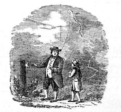
LONDON: PRINTED BY WILLIAM CLOWES AND SONS, LIMITED,
STAMFORD STREET AND CHARING CROSS.

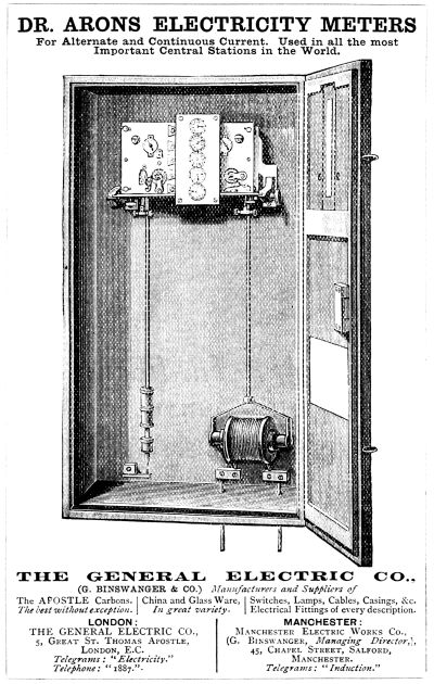
Footnotes:
[1] Unit; see page 7.
[3] 1000 watts.
[4] Hedges on the Supply of Electricity by Local Authorities. Proceedings of Association of Municipal and Sanitary Engineers and Surveyors, vol. ix. (1882-83), p. 159.
[5] From Industries.
[6] Kilowatt equals 1,000 watts.
Transcriber's Notes:
The illustrations have been moved so that they do not break up paragraphs and so that they are next to the text they illustrate.
Typographical errors have been silently corrected.
The three advertisements at the beginning of the book have been moved in front of the thirteen advertisements at the back of the book.